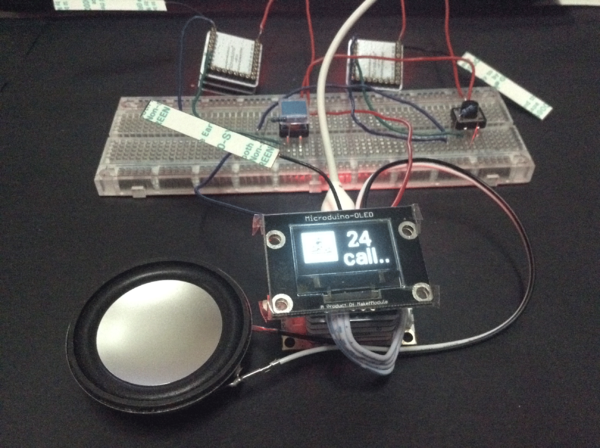
Microduino Ward Calling System
|
PurposeThe course will show you how to use Microduino to simulate a ward calling system. Equipment
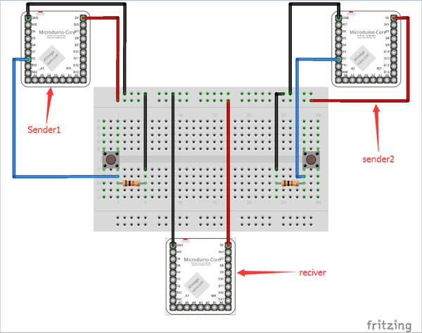
SchematicThere are two senders—sender 1 and sender 2 in the picture—for patients to send signals. Modules to be stacked:
One receiver for nurses to check for patient help.
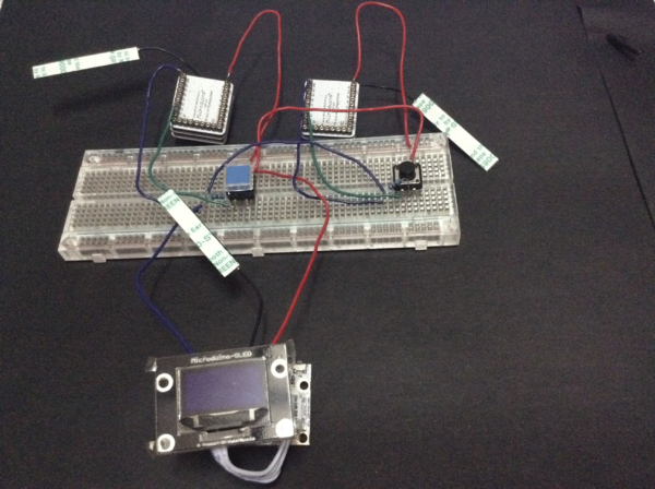
ProgramDebuggingStep 1: Build the circuit according to schematic, as follows:
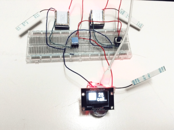
Meantime, press button marked with sender 2 in the schematic and the readings will be displayed on receiver OLED:
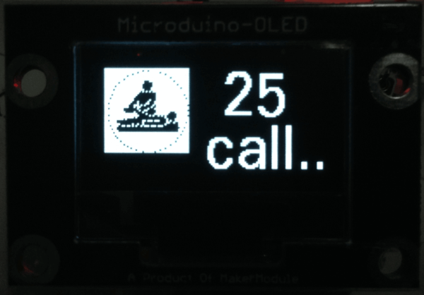
If readings showed on OLED were defined in the code, it means the calling of No. 25 patient is successful.
The 16 hexadecimal of the picture showed on OLED is produced through PCtolCD. The detailed method can refer to: Lesson 2--Microduino OLED Usage Step 4: By adding voice prompt function, medical workers can get voice notice when someone calls. Stack Microduino-Amplifier and Microduino-SD on the basis of the three modules, as follows: Re-download MicroduinoHospitalCallReciverSound.ino program to Core+. Save audio files you want to play into SD card of Microduino-SD. As for how to make audio files, please refer to: Microduino LM4863 Music player -301KIT
ResultHere we make a simple wireless ward calling system. Video |
