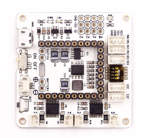
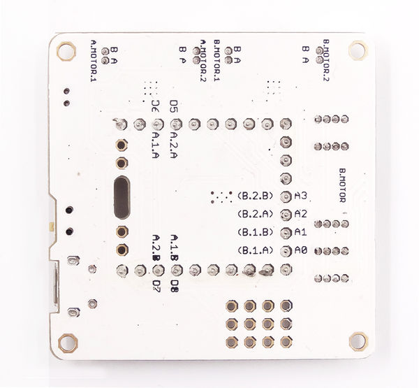
Microduino-Shield Robot/zh
853387039@qq.com(讨论 | 贡献)2014年11月20日 (四) 15:43的版本 (Created page with "{{Language|Microduino-Robot/zh}} {| style="width: 800px;" Microduino-ROBOT板子作为机器人控制板, 将配合Microduino-Core+/zh、Microduino-Motor/zh或Micro...")
| Language | English |
|---|
|
文件:Microduino- Robot -rect.jpg Microduino- Robot 特色
规格
文档开发
示例程序: //=========M.A=============//
int mic_left_A = 7;
int mic_right_A = 5;
int mic_head_A = 8;
int mic_back_A = 6;
//=========M.B=============//
/*
int mic_left_B = 22;
int mic_right_B =18;
int mic_head_B = 23;
int mic_back_B = 19;
*/
void setup() {
pinMode(mic_left_A,OUTPUT);
pinMode(mic_right_A,OUTPUT);
pinMode(mic_head_A,OUTPUT);
pinMode(mic_back_A,OUTPUT);
}
void loop() {
head();
delay(1500);
back();
delay(1500);
left();
delay(1500);
right();
delay(1500);
}
void head()
{
digitalWrite(mic_left_A,LOW);
digitalWrite(mic_right_A,HIGH);
digitalWrite(mic_head_A,HIGH);
digitalWrite(mic_back_A,LOW);
}
void left()
{
digitalWrite(mic_left_A,HIGH);
digitalWrite(mic_right_A,LOW);
digitalWrite(mic_head_A,HIGH);
digitalWrite(mic_back_A,LOW );
}
void right()
{
digitalWrite(mic_left_A,LOW);
digitalWrite(mic_right_A,HIGH);
digitalWrite(mic_head_A,LOW);
digitalWrite(mic_back_A,HIGH);
}
void back()
{
digitalWrite(mic_left_A,HIGH);
digitalWrite(mic_right_A,LOW);
digitalWrite(mic_head_A,LOW);
digitalWrite(mic_back_A,HIGH);
}
void stoop()
{
digitalWrite(mic_left_A,LOW);
digitalWrite(mic_right_A,LOW);
digitalWrite(mic_head_A,LOW);
digitalWrite(mic_back_A,LOW);
}
#include <AccelStepper.h>

const int ENPin_A =8  ;      // the number of the LED pin
const int ENPin_B =23  ;      // the number of the LED pin

int motorSpeed = 9600; //maximum steps per second (about 3rps / at 16 microsteps)
int motorAccel = 80000; //steps/second/second to accelerate

int motorDirPin_A = 5; //digital pin 5
int motorStepPin_A = 7; //digital pin 7
int motorDirPin_B = 18; //digital pin 5
int motorStepPin_B = 22; //digital pin 7

//set up the accelStepper intance
//the "1" tells it we are using a driver
AccelStepper stepper_A(1, motorStepPin_A, motorDirPin_A);
AccelStepper stepper_B(1, motorStepPin_B, motorDirPin_B);

void setup(){
  pinMode(ENPin_A, OUTPUT);
  pinMode(ENPin_B, OUTPUT);
  stepper_A.setMaxSpeed(motorSpeed);
  stepper_A.setSpeed(motorSpeed);
  stepper_A.setAcceleration(motorAccel);

  stepper_A.moveTo(3200); //move 32000 steps (should be 10 rev)

  stepper_B.setMaxSpeed(motorSpeed);
  stepper_B.setSpeed(motorSpeed);
  stepper_B.setAcceleration(motorAccel);

  stepper_B.moveTo(3200); //move 32000 steps (should be 10 rev)

}

void loop(){
  digitalWrite(ENPin_A, LOW);
  digitalWrite(ENPin_B, LOW);
  //if stepper is at desired location
  if (stepper_A.distanceToGo() == 0){
    //go the other way the same amount of steps
    //so if current position is 400 steps out, go position -400
    stepper_A.moveTo(-stepper_A.currentPosition());
  }
  //these must be called as often as possible to ensure smooth operation
  //any delay will cause jerky motion
  stepper_A.run();

  if (stepper_B.distanceToGo() == 0){
    //go the other way the same amount of steps
    //so if current position is 400 steps out, go position -400
    stepper_B.moveTo(-stepper_B.currentPosition());
  }
  //these must be called as often as possible to ensure smooth operation
  //any delay will cause jerky motion
  stepper_B.run();
}
应用购买历史图库
视频 |

