“Lazy Donkey”的版本间的差异
(→Overview) |
(→Hardware Buildup) |
||
| 第71行: | 第71行: | ||
</source> | </source> | ||
==Hardware Buildup== | ==Hardware Buildup== | ||
| − | *Setup | + | *Setup 1:Use the below diagram as reference and connect the sensors into the corresponding ports on the Hub module. |
| − | |||
| − | corresponding ports on the Hub module. | ||
[[File: _304_DozingDonkey _hub.jpg|600px|center]] | [[File: _304_DozingDonkey _hub.jpg|600px|center]] | ||
| − | *Setup 2:Connect the motor to the Motor module as shown above. | + | *Setup 2:Connect the motor to the Motor module as it is shown above. |
[[File: _304_DozingDonkey _Motor.jpg|600px|center]] | [[File: _304_DozingDonkey _Motor.jpg|600px|center]] | ||
| − | *Setup 3:According to your project needs, you can attach the motor accessories for | + | *Setup 3:According to your project needs, you can attach the motor accessories for attachment to other devices. |
| − | |||
| − | attachment to other devices. | ||
[[File: _304_DozingDonkey _Motor1.jpg|400px|center]] | [[File: _304_DozingDonkey _Motor1.jpg|400px|center]] | ||
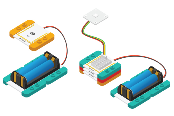
| − | *Setup 4:Connect the activated Battery | + | *Setup 4:Connect the activated Battery box to your Battery Management module. |
[[File:CoreUSB_Ble_steup2.jpg|600px|center]] | [[File:CoreUSB_Ble_steup2.jpg|600px|center]] | ||
| − | *Setup 5:Stack all the modules together in any order you like. Congratulations, you have | + | *Setup 5:Stack all the modules together in any order you like. Congratulations, you have finished building the circuit! |
| − | |||
| − | finished building the circuit! | ||
[[File: _304_DozingDonkey _steup-ok-E.jpg|600px|center]] | [[File: _304_DozingDonkey _steup-ok-E.jpg|600px|center]] | ||
2015年10月25日 (日) 04:43的版本
| Language | English |
|---|
目录OverviewMr. donkey is always too lazy to work. Only by knocking on the desk will he get to work. SchematicUse shock sensor detects the beat, and then let the motor run some distance the donkey forward. User can set the speed and duration time of donkey running. Equipment
Preparation
program should have successfully been uploaded into the CoreUSB. Program description
#define motor_pinB 6  //Motor 1
#define motor_pinA 8  //Motor 1

//#define servo_pinB 5   //Motor 2
//#define servo_pinA 7   //Motor 2

const int vibrationPin = 10;  // Shack sensor
adjust to any value from 0 to 255 (recommended value not less than 60, or may be triggering Movies sensor stability).
modify it as needed. void fullForward() {
//digitalWrite(motor_pinB, HIGH);
analogWrite(motor_pinB,255);//0-255
digitalWrite(motor_pinA, LOW);
delay(1000);
}
Hardware Buildup
ResultTapping the table, shock sensor detects vibrations, the donkey moves forward 1 second. Video |
