“Microduino Video output”的版本间的差异
| 第43行: | 第43行: | ||
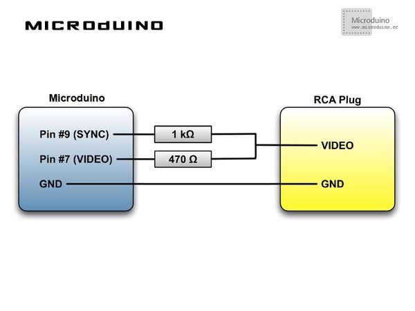
==Schematic Diagram== | ==Schematic Diagram== | ||
| − | [[File: | + | [[File:Microduino视频输出原理图.jpg|600px|center|thumb]] |
| − | + | [[File:视频输出原理图.jpg|600px|center|thumb]] | |
| − | [[File: | ||
| 第78行: | 第77行: | ||
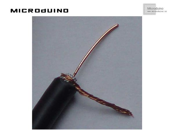
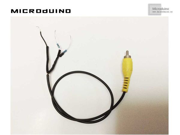
The two wires can be made as follows: | The two wires can be made as follows: | ||
| − | [[File: | + | [[File:RCA线制作.jpg|600px|center|thumb]] |
Step 2:To connect 1000 Ω and 470 Ω to two wires divided from the signal wire, according to the schematic diagram. The connecting line finally made looks just like this: | Step 2:To connect 1000 Ω and 470 Ω to two wires divided from the signal wire, according to the schematic diagram. The connecting line finally made looks just like this: | ||
| − | [[File: | + | [[File:电阻连接RCA线图.jpg|600px|center|thumb]] |
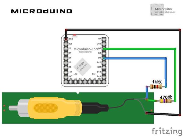
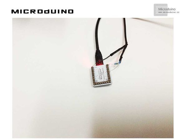
Step 3:To connect RCA to Microduino, connect 1000 Ω to D9, 470 Ω to D7, and Gnd to GND, as follows: | Step 3:To connect RCA to Microduino, connect 1000 Ω to D9, 470 Ω to D7, and Gnd to GND, as follows: | ||
| − | [[File: | + | [[File:Microduino连接RCA线图.jpg|600px|center|thumb]] |
The connector of RCA connecting to the AV connector of your TV is yellow and very easy to recognize. | The connector of RCA connecting to the AV connector of your TV is yellow and very easy to recognize. | ||
| 第101行: | 第100行: | ||
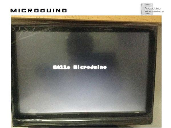
A line, a circle and “Hello Microduino” will be displayed recurrently on TV. As follows: | A line, a circle and “Hello Microduino” will be displayed recurrently on TV. As follows: | ||
| − | [[File: | + | [[File:电视输出图像hello microduino.jpg|600px|center|thumb]] |
| − | [[File: | + | [[File:电视输出图像.jpg|600px|center|thumb]] |
==Notice== | ==Notice== | ||
2014年5月6日 (二) 03:19的最新版本
|
目录Outline
Bill of Materials
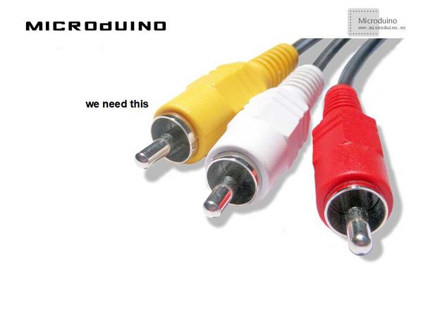
RCA CableBefore we start to build a video signal, we must connect Microduino to a TV. The cheapest and the simplest solution is RCA cable (sometimes called cinch cable) which is used to send audio or video signals. In the chart below, you can a RCA cable with three connectors. These cables typically transmit sound (red and white connectors) and video (yellow connector). In this case, all we need is the cable of the yellow connector. Video FormatVideo format consists of PAL and NTSC. The former is mainly used in China:
Schematic Diagram
Program
tv.select_font(font4x6);//Set front tv.clear_screen();//Clear tv.draw_line(0, 10, WIDTH - 1, HEIGHT - 1, WHITE);//Draw line tv.draw_rect(0, 10, WIDTH - 11, HEIGHT - 11, WHITE);//Draw Rectangle tv.draw_circle(WIDTH / 2, HEIGHT / 2, 20, WHITE);//Draw circle
DebuggingStep 1:Since Microduino has no RCA jack field, so how to connect Microduino to TV is a problem. Surely, we can add a RCA jack field on Microduino. However, we will use another way to connect cable to pins of Microduino.
The outermost layer is the ground wire. The signal wire is in the middle, which is protected by a layer of insulation.
Step 3:To connect RCA to Microduino, connect 1000 Ω to D9, 470 Ω to D7, and Gnd to GND, as follows: The connector of RCA connecting to the AV connector of your TV is yellow and very easy to recognize. Step 4:A library function will be needed to solve video encoding output problems of PAL and NTSC: http://code.google.com/p/arduino-tvout/ To download the code and compile successfully. Step 5:To run the code and see what happens on the screen of the TV. ResultA line, a circle and “Hello Microduino” will be displayed recurrently on TV. As follows: Notice
Video |
