|
Outline
- Project:Microduino TV Output
- Purpose:The course will teach us how to use Microduino to connect your TV and send video output to the screen in the form of PAL or NTSC format.
- Difficulty:Middle
- Time-consuming:1 hour
- Maker:Microduino Studio-ray
- Source: Make Your Own Video Game System by Maik Schmidt http://pragprog.com/magazines/2011-08/make-your-own-video-game-system/
Bill of Materials
- Other Hardware Equipments
- A TV set with AV interface
- An USB cable
- A number of wire jumper
- A RCA cable
- A resistance of 1000Ω
- A resistance of 470 Ω
RCA Cable
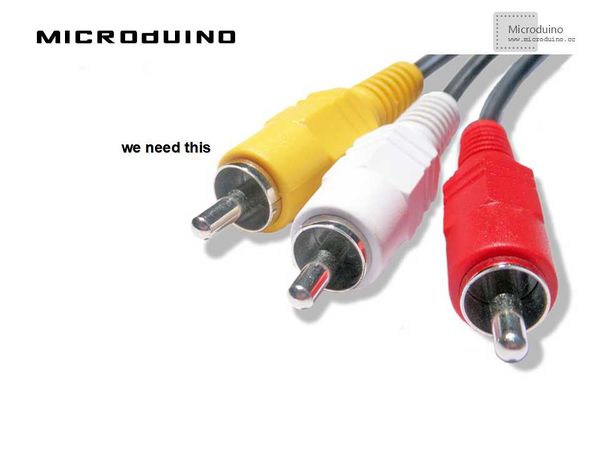
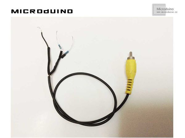
Before we start to build a video signal, we must connect Microduino to a TV. The cheapest and the simplest solution is RCA cable (sometimes called cinch cable) which is used to send audio or video signals. In the chart below, you can a RCA cable with three connectors.
These cables typically transmit sound (red and white connectors) and video (yellow connector). In this case, all we need is the cable of the yellow connector.
Video Format
Video format consists of PAL and NTSC. The former is mainly used in China:
- PAL is a method of color frequency in the television broadcasting, whose full name is Phase Alternating Line). Most parts of the world are based on the PAL format in addition to North America and parts of the East Asia using the NTSC format, as well as the Middle East and Eastern Europe adopting SECAM format. PAL was firstly proposed by the German, Walter Bruch in 1963, who worked for Telefunken.
- NTSC is an abbreviation for National Television Standards Committee, which is responsible for developing a United States standard television broadcasting transmitting and receiving protocol. Besides, there are two sets of standards : PAL and SECAM-which are used for other countries in the world. There is no significant change about NTSC standard in addition to adding new parameters of color signal since coming into being. Moreover, NTSC signal can not be directly compatible with computer systems.
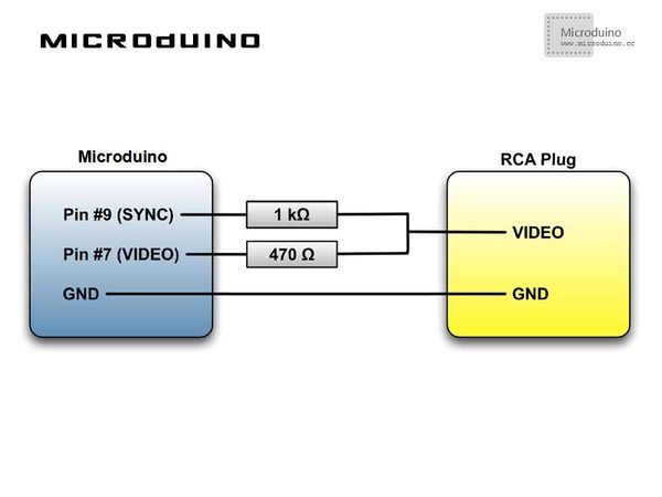
Schematic Diagram
Program
https://github.com/Microduino/Microduino_Tutorials/tree/master/Microduino_Advanced_Tutorial/MicroduinoTVOut
tv.begin(PAL, WIDTH, HEIGHT);//Sett output format, length and width
tv.select_font(font4x6);//Set front
tv.clear_screen();//Clear
tv.draw_line(0, 10, WIDTH - 1, HEIGHT - 1, WHITE);//Draw line
tv.draw_rect(0, 10, WIDTH - 11, HEIGHT - 11, WHITE);//Draw Rectangle
tv.draw_circle(WIDTH / 2, HEIGHT / 2, 20, WHITE);//Draw circle
Debugging
Step 1:Since Microduino has no RCA jack field, so how to connect Microduino to TV is a problem. Surely, we can add a RCA jack field on Microduino. However, we will use another way to connect cable to pins of Microduino.
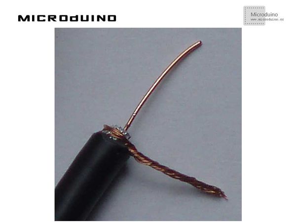
Cut your cable, you will find RCA cable includes signal wire and ground wire.
The outermost layer is the ground wire. The signal wire is in the middle, which is protected by a layer of insulation.
The two wires can be made as follows:
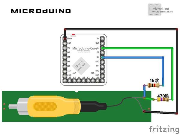
Step 2:To connect 1000 Ω and 470 Ω to two wires divided from the signal wire, according to the schematic diagram. The connecting line finally made looks just like this:
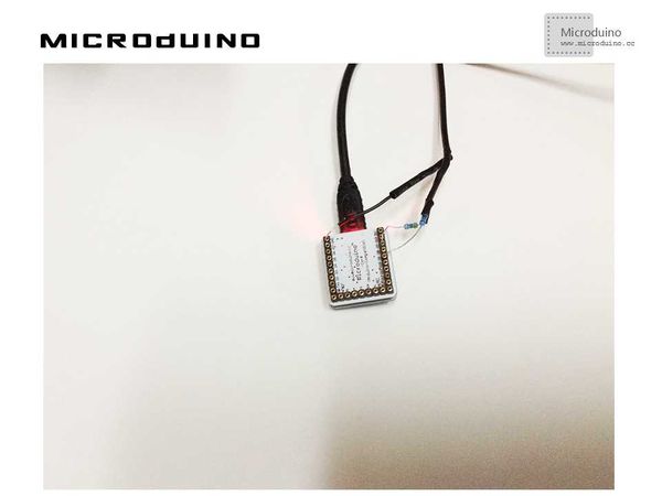
Step 3:To connect RCA to Microduino, connect 1000 Ω to D9, 470 Ω to D7, and Gnd to GND, as follows:
The connector of RCA connecting to the AV connector of your TV is yellow and very easy to recognize.
Step 4:A library function will be needed to solve video encoding output problems of PAL and NTSC: http://code.google.com/p/arduino-tvout/
To download the code and compile successfully.
Step 5:To run the code and see what happens on the screen of the TV.
Result
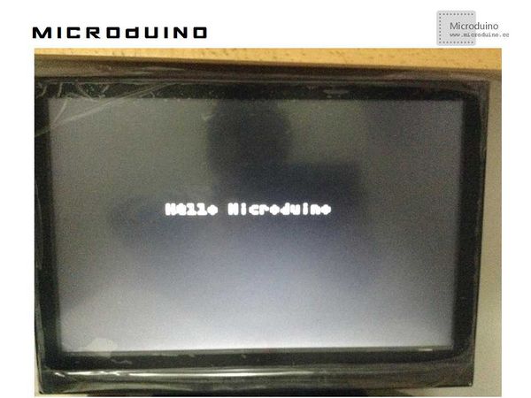
A line, a circle and “Hello Microduino” will be displayed recurrently on TV. As follows:
Notice
- Mistakes should be avoided during welding resistance
Video
http://v.youku.com/v_show/id_XNzAxOTc5NTA4.html
| 