RGB light
| Language | English |
|---|
ObjectiveThis tutorial will teach you using the Processing to control RGB LED, then use a color selector to control the color. Equipment
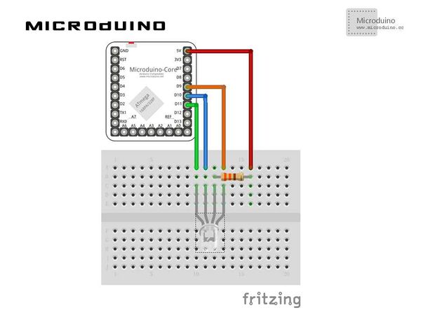
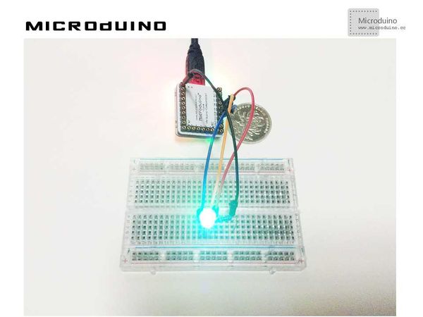
SchematicProgramhttps://github.com/Microduino/Microduino_Tutorials/tree/master/Microduino_Processing/RGBLED DebugStep 1:Set up hardware system, as follows:
//Display palette function void drawShadeWheel() {
for (int j = 0; j < steps; j++) {
color[] cols = {
color(255-(255/steps)*j, 255-(255/steps)*j, 0),
color(255-(255/steps)*j, (255/1.5)-((255/1.5)/steps)*j, 0),
color(255-(255/steps)*j, (255/2)-((255/2)/steps)*j, 0),
color(255-(255/steps)*j, (255/2.5)-((255/2.5)/steps)*j, 0),
color(255-(255/steps)*j, 0, 0),
color(255-(255/steps)*j, 0, (255/2)-((255/2)/steps)*j),
color(255-(255/steps)*j, 0, 255-(255/steps)*j),
color((255/2)-((255/2)/steps)*j, 0, 255-(255/steps)*j),
color(0, 0, 255-(255/steps)*j),
color(0, 255-(255/steps)*j, (255/2.5)-((255/2.5)/steps)*j),
color(0, 255-(255/steps)*j, 0),
color((255/2)-((255/2)/steps)*j, 255-(255/steps)*j, 0)
};
for (int i = 0; i < segs; i++) {
fill(cols[i]);
arc(width/2, height/2, radius, radius,
interval*i+rotAdjust, interval*(i+1)+rotAdjust);
}
radius -= segWidth;
}
}
 boolean mouseOverRect() { // Test if mouse is over square
   return ((mouseX >= 10) && (mouseX <= 190) && (mouseY >= 10) && (mouseY <=190));
 }
//Got the RGB value, write to pin9,10,11 void draw() {
// nothing happens here
if (mouseOverRect() == true)
{
color targetColor = get(mouseX, mouseY);
// get the component values:
int r = int(red(targetColor));
int g = int(green(targetColor));
int b = int(blue(targetColor));
// analogWirte to pin
arduino.analogWrite(9, r);
arduino.analogWrite(10, g);
arduino.analogWrite(11, b);
}
}
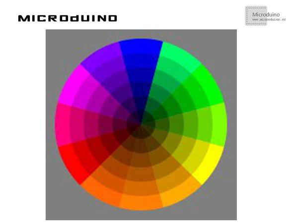
Step 3: Compile the code and download it. Step 4: After runing, will display a palette, click on the color of your choice, observe the color of the LED light. ResultA color selector will display on screen, as follows:
Video |


