|
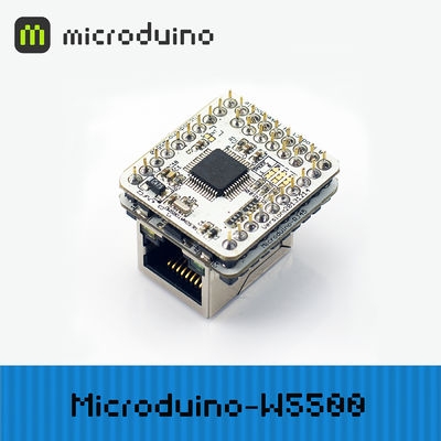
Microduino-W5500 is the Ethernet control module, developed by adopting W5500 network chip. Only when Microduino-W5500 is stacked with Microduino-RJ45 can it form a
complete network module. It can not be used individually.
Features
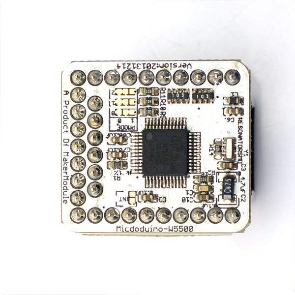
- Microduino-W5500 is a brand new all-hardware TCP / IP protocol stack network chip after W5100, W5200 and W5300. It is the best choice of the embedded Ethernet with lower power consumption and operation temperature as well as improved workmanship
- Adopting U-shaped 27-pin Microduino standard interface, Microduino-W5500 can be stacked with Microduino-RJ45 and be delivered ready to plug in, making it smaller.
- With open source hardware circuit design, Microduino-W5500 is compatible with Arduino IDE development environment. ?
- With uniform Microduino interface specification and rich peripheral modules, it is very convenient and flexible for Microduino-W5500 to quickly connect with other modules and sensors corresponding with Microduino interface specification.
- 2.54mm (0.1 inch) pin pitch, compatible to pegboard.
Specification
- Communication Protocol
- Supporting hardware TCP/IP protocol: TCP, UDP, ICMP, IPv4, ARP, IGMP, PPPoE ?
- Supporting eight independent ports(Socket) for simultaneous communication ?
- Embedded 10BaseT/100BaseTX Ethernet PHY
- Supporting automatic negotiation (10/100-Based full and Half-Duplex modes) ?
- Operation Features ?
- Supporting power down mode ?
- Supporting WOL ?
- Supporting automatic reply(full and half-duplex modes)
- Update Speed
- Supporting high-speed serial peripheral interface ?
- 32K bytes inside for sending and receiving cache
- Interface Features
- TTL level input ?
- Single power supply: 3.3V;
- Not supporting IP fragmentation
Status Indication
- Two programmable LED outputs used for connecting, sending, receiving conflicts as well as full and half-duplex modes.
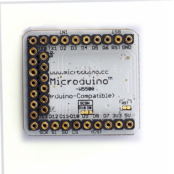
| Pin Name of Microduino-W5500 |
Microduino Pins |
Function
|
| SO |
D11 |
Data output of SPI interface
|
| SI |
D12 |
Data input of SPI interface
|
| SCK |
D13 |
Clock input of SPI interface ?
|
| CS |
D10/D8 |
Chip select input of SPI interface
|
| RESET |
RESET |
Reset input
|
Documents
Development
Arduino libraries and support packages:
https://github.com/Microduino/Microduino_Tutorials/tree/master/Microduino_Libraries/_02_Microduino_Ethernet_WIZ
Widely applied in:
Home network device: STB,PVR and digital media adapter?
Security system: DVR,IPC and kiosk
Factory and building automation systems, medical monitoring equipment and embedded server
Application
Networking Microduino core modules via sample programs:
Preparation
- All hardware needed: Microduino FT232R, Microduino Core, Microduino-W5500, router and network cable;
- All software needed:Higher version of Arduino IDE (1.0), libraries, debugging programs offered by Microduino (Arduino);
- Put the downloaded libraries into the folder of Arduino IDE installation libraries;
- Delete the previous Ethernet libraries;
- Stack all modules together and connect the LAN port and the network interface of Microduino-RJ45 module via internet cable;
Step 1:Acquire your IP address
- Start Arduino IDE, open sample program "DhcpAddressPrinter" and choose Microduino Core(Atmega328P@16M,5V) as the board; Download after successful compiling;
- Open serial monitor(Please note that the baud rate is 9,600 bits ), you can see "My IP address: XXX.XXX.XX.XXX." Then you can get your IP.
Step 2:Connect Microduino core modules through network and acquire web page information
- Open sample program"WebClient" and change the code address "IPAddress ip(192,168,0,177)" to the IP address that can readable, and then download after successful compiling.
- Open serial monitor after successful download, you can see "connecting...". If the connection goes well, you can print out the data acquired from network, such as
address, server, time and so on.
Purchase
History
Picture
Front
Back
Video
|


