Lesson 24--Microduino & Operational Amplifier-- Noninverting Scaling Operation
Noninverting Scaling Operation Circuit Demo
目录PurposeThe tutorial offers the basic knowledge of the operational amplifier. The example adopts the noninverting scaling operation circuit, which amplifies one dry cell battery to a certain ratio and detect the two voltage signals with Microduino. EquipmentMicroduino-Core is the 8-bit single-chip development core board with Atmel ATmega328P as the core, which is an open and Arduino Uno compatible controller. Microduino-USBTTL is the program download module, capable of connecting with Microduino-Core or Microduino-Core+ and making the modules communicate with the computer. It uses MicUSB as the download interface, which is also the smallest part of Microduino. Microduino is just as small as a quarter. Besides, the downlaod cable is just like the USB cable of most smart phones, easy to use.
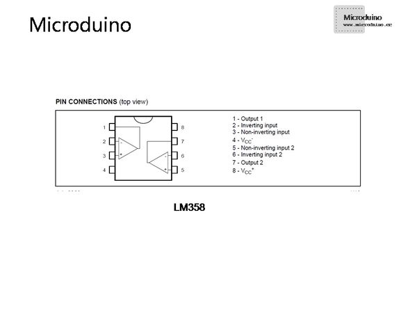
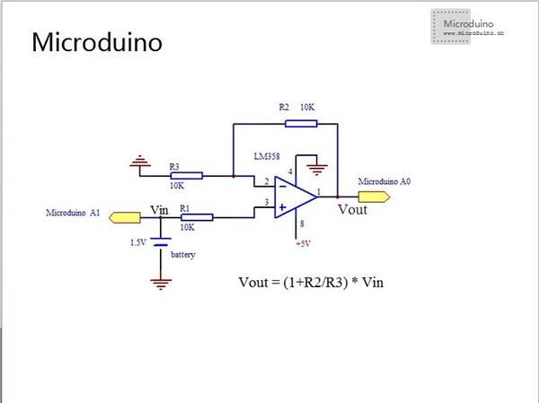
LM358 Operational AmplifierLM358 is a common chip, which contains two independent operation amplifier circuits inside. The operational amplifier A adopts pin 1 as the output end, pin 2 as the inverting output end and pin 3 as the noninverting input end. The operational amplifier B chooses pin 7 , pin 6 and pin 5 as the output end, inverting output end and noninverting input end respectively. The operational amplifier A and B share the same power end (Negative pin 4, positive pin 8). The chip can achieve both single and dual power supply, outputting the maximum voltage of 32V and +Vcc=+16V or -Vcc=-16V respectively. In the example, the negative of the battery connects with LM358 to the ground and the operational amplifier has single power supply for option. LM358文档下载:文件:358pdf.pdf Dry BatteryThe dry battery is very common in our lives, whose electrolyte is non-liquid. That is why it gets the game. The dry battery can be supplied to the flashlight, radio, camera and electric toys. Here in the example is the AA battery. A cell of dry battery has a voltage of about 1.5 V, a cell of storage battery about 2V and the phone battery about 3.7V. SchematicThe output voltage of the LM358’s pin 1 is Vout=Vin*(1+R2/R3). The noninverting scaling operation circuit owns high-input and low-output resistance. (High-input resistance means little influence on the signal source and low-output means strong load capacity.) Notably. No matter how we change the values of R2 and R3, the output voltage of the LM358’s pin 1 won’t be higher than that of the power. (The voltage of the power in the example is 5V.) Program///A0 connect amp output
///A1 connect single battery output
int anaValueSingleBa; //single battery value map(0--1023)
int anaValueAmp; //amp value map(0--1023)
float anaVoltageSingleBa; //single battery voltage
float anaVoltageAmp; //amp output voltage
void setup()
{
Serial.begin(9600);
}
void loop()
{
anaValueSingleBa=analogRead(A1);
anaVoltageSingleBa=anaValueSingleBa/1023.0*5;
Serial.print("Single battery voltage is ");
Serial.print(anaVoltageSingleBa);
Serial.println("V");
delay(1000);
anaValueAmp=analogRead(A0);
anaVoltageAmp=anaValueAmp/1023.0*5;
Serial.print("Amp output voltage is ");
Serial.print(anaVoltageAmp);
Serial.println("V");
delay(1000);
}
Debugging
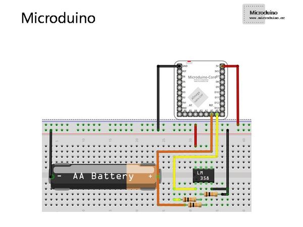
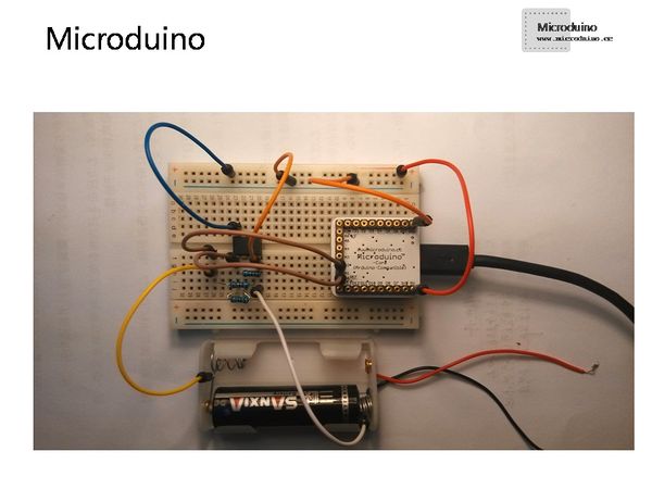
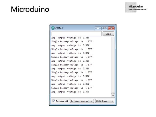
ResultJust build the circuit according to the schematic After program downlaod, you can watch the output voltage in the serial monitor of Arduino IDE. Contrast Formulae:Vout=Vin*(1+R2/R3) for ease of analyzing experimental data. Video |
