Lesson 11--Microduino Infrared Controls Servo Angle
| Language | English |
|---|
ObjectiveThis lesson will teach you control the servo by infrared. Equipment
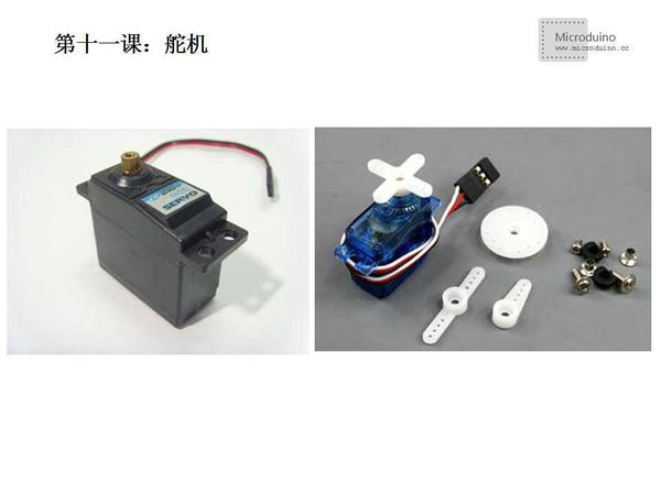
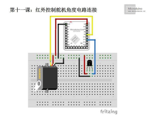
Servo is a set of automatic control system which consists of DC motor, gear set, sensor and control circuit. By sending a signal, the output shaft will rotate specified angle. Generally servo has a maximum rotation angle (such as 180 degrees). The mainly difference between a common DC motor is taht DC motor is circular rotation, servo only can rotate within a certain Angle, can't rotate as circle (digital servo can switch in the servo model and motor model, doesn't have this problem). Common DC motor can't return the rotation angle information, and servo can be. Usage is different also, common DC motor is made power with the whole circle turn, servo is used to control an objuect to rotate a certain angle (such as robot joints). SchematicIn schematic, the black line is the ground wire and need connect to GNU, red line is the power line to 5V voltage, the blue line is the infrared receiver signal line, the yellow line is the servo signal line. ProgramDownload program: https://github.com/Microduino/Microduino_Tutorials/tree/master/Microduino_Advanced/MicroduinoIRControlServeAngle #include <IRremote.h>
#include <Servo.h>
int action;
int deg=0;
int t;
int RECV_PIN = 11;//Defien the infrared receive pin
IRrecv irrecv(RECV_PIN);
Servo servo;
decode_results results;
int deckey(unsigned long t)
{
switch(t){
case 0xFD08F7://Button 1 encoding
return 1;
break;
case 0xFD8877://Button 2 encoding
return 2;
break;
case 0xFD48B7://Button 3 encoding
return 3;
break;
case 0xFD28D7://Button 4 encoding
return 4;
break;
case 0xFDA857://Button 5 encoding
return 5;
break;
case 0xFD6897://Button 6 encoding
return 6;
break;
case 0xFD18E7://Button 7 encoding
return 7;
break;
case 0xFD9867://Button 8 encoding
return 8;
break;
case 0xFD58A7://Button 9 encoding
return 9;
break;
default:
return 0;
break;
}
}
void setup()
{
Serial.begin(9600);
irrecv.enableIRIn(); // Initialize the infrared receiver
servo.attach(9);
servo.write(0);
t=0;
}
void loop() {
deg=servo.read();
if (irrecv.decode(&results))
{
action=deckey(results.value);
Serial.println(results.value, HEX);//In hexadecimal output to receive code with a new line
Serial.println(action);
Serial.println();//In order to easy observe the output increase a blank line
switch(action)
{
case 1:
servo.write(0);
break;
case 2:
servo.write(20);
break;
case 3:
servo.write(40);
break;
case 4:
servo.write(60);
break;
case 5:
servo.write(80);
break;
case 6:
servo.write(100);
break;
case 7:
servo.write(120);
break;
case 8:
servo.write(140);
break;
case 9:
servo.write(160);
break;
}
delay(10);
irrecv.resume();
}
}
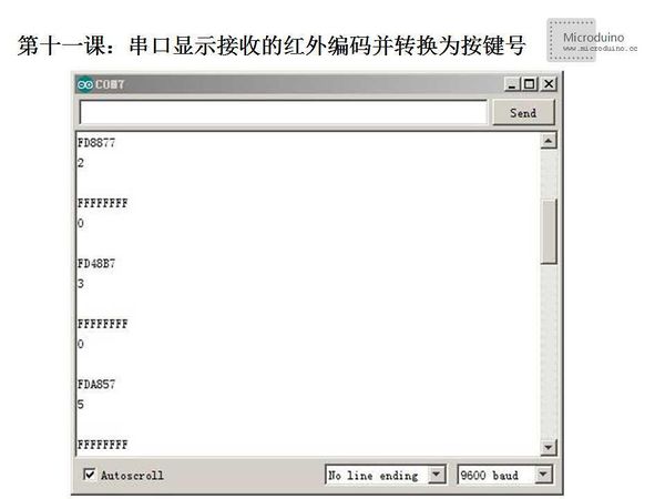
DebugStep 1:Download IRremote library [1] Step 2:Uncompress the library to libraries folder of Arduino IDE Step 3: Set up the circuit; Step 4: open the serial monitor, the remote control towards to the infrared receiver button, infrared codes will be shown. ResultPress the button 1,2,3,4..., servo will rotate. Video |


