“Microduino-Shield Cube-S2/zh”的版本间的差异
小 (Wasdpkj@hotmail.com moved page Microduino-Shield Cube-S2 to Microduino-Shield Cube-S2/zh) |
502748957@qq.com(讨论 | 贡献) |
||
| 第7行: | 第7行: | ||
| + | ==特色== | ||
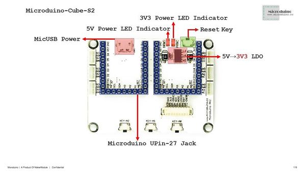
| + | *包含 [[Microduino-TFT]] 与 [[Microduino0-OLED](IIC)]的8pin/4pin接口;; | ||
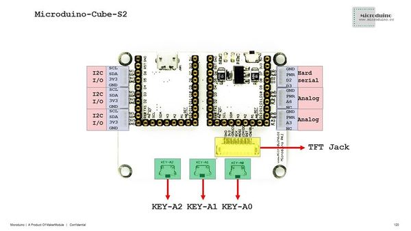
| + | *板上有三个模拟按键A0/A1/A2 | ||
| + | *板上复位按键 | ||
| + | *两组UPIN27接口用于连接其它Microduino标准模块 | ||
| + | ==规格== | ||
| + | *电气规格 | ||
| + | **MicroUSB接口用于供电; | ||
| + | **3.3V稳压(AMS1117); | ||
| + | **PWR电压可通过跳线选择5V或3.3V(默认3.3V); | ||
| + | **供电电压5V; | ||
| + | *扩展 | ||
| + | **三路IIC饥接口; | ||
| + | **D2/D3接口,可用于串口1调试(Serial1); | ||
| + | **两路模拟传感器接口A3/A6; | ||
| + | **1.27mm传感器插线座; | ||
| + | [[file:Microduino-Cube-S2-Pinout1Big1.jpg|600px|thumb|center|Microduino-Cube-S2]] | ||
| + | [[file:Microduino-Cube-S2-Pinout2Big1.jpg|600px|thumb|center|Microduino-Cube-S2-Pinout]] | ||
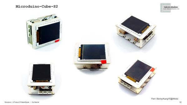
| + | [[file:Microduino-Cube-S2-Pinout3Big2.jpg|600px|thumb|center|Microduino-Cube-S2-Pinout]] | ||
| + | ==文档== | ||
| + | 主要元器件: | ||
| + | *3.3V LDO手册: '''[[File:ASM1117.pdf | AMS1117手册]]''' | ||
| + | ==开发== | ||
| + | 该板是特别为[[Microduino-TFT]]设计的,可与其他Microduino UPIN27接口规范的模块一同使用。 | ||
| + | [[file:Microduino-Cube-S2-Pinout4.jpg|600px|thumb|center|Microduino-Cube-S2]] | ||
| + | ==应用== | ||
| + | ===测试[[Microduino-TFT]]=== | ||
| + | *所需硬件: [[Microduino-USBTTL]], [[Microduino-Core]], [[Microduino-Cube-S2]] 和[[Microduino-OLED]] | ||
| + | *所需软件: Microduino IDE(1.6.7以上) | ||
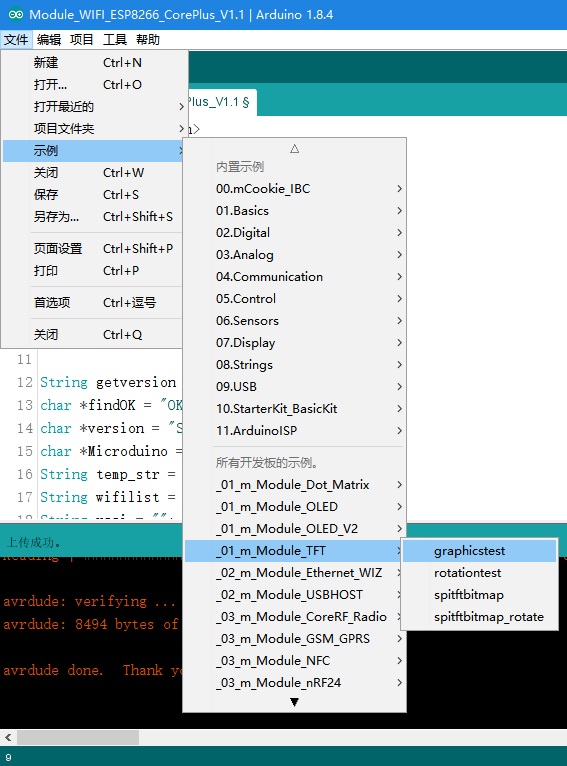
| + | *打开IDE,找到示例→Module_TFT | ||
| + | [[file:S2 TFT TEST.jpg|600px|thumb|center]] | ||
| + | *开发板选择Microduino/mCookie Device,型号选择Core(Atmega328P@16M,5V)之后下载程序至硬件中即可观察效果; | ||
| + | ==购买== | ||
| + | ==历史== | ||
| − | + | ==图库== | |
| − | == | ||
| − | |||
| − | |||
| − | |||
| − | |||
| − | |||
| − | |||
| − | |||
| − | |||
| − | |||
| − | |||
| − | |||
| − | |||
| − | |||
| − | |||
| − | |||
| − | |||
| − | |||
| − | |||
| − | |||
| − | |||
| − | |||
| − | |||
| − | |||
| − | |||
| − | |||
| − | |||
| − | |||
| − | |||
| − | |||
| − | |||
| − | |||
| − | |||
| − | |||
| − | |||
| − | |||
| − | |||
| − | |||
| − | |||
| − | |||
| − | |||
| − | |||
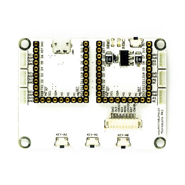
[[file:Microduino-Cube-S2-F.JPG|thumb|600px|center|Microduino-Cube-S2 Front]] | [[file:Microduino-Cube-S2-F.JPG|thumb|600px|center|Microduino-Cube-S2 Front]] | ||
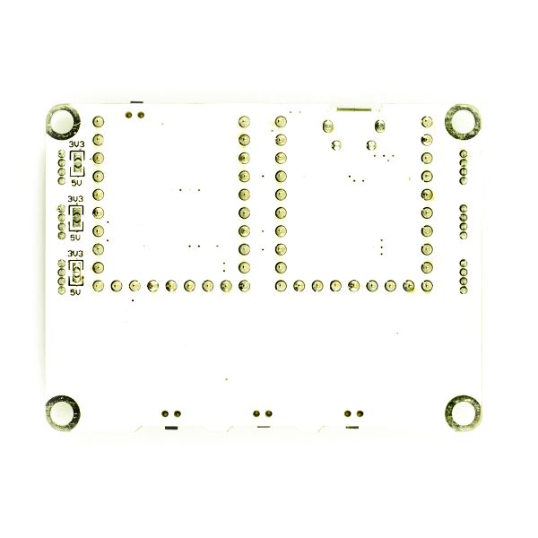
[[file:Microduino-Cube-S2-b.JPG|thumb|600px|center|Microduino-Cube-S2 Back]] | [[file:Microduino-Cube-S2-b.JPG|thumb|600px|center|Microduino-Cube-S2 Back]] | ||
| − | |||
|} | |} | ||
2018年6月19日 (二) 08:52的版本
| Language | English |
|---|
|
特色
规格
文档主要元器件:
开发该板是特别为Microduino-TFT设计的,可与其他Microduino UPIN27接口规范的模块一同使用。 应用测试Microduino-TFT
购买历史图库 |

