Lesson 14--Microduino Digital Tube Experiment 1 - Digital Dice
| Language | English |
|---|
ObjectiveThis lesson will teach you use digital to display number by Microduino. Equipment
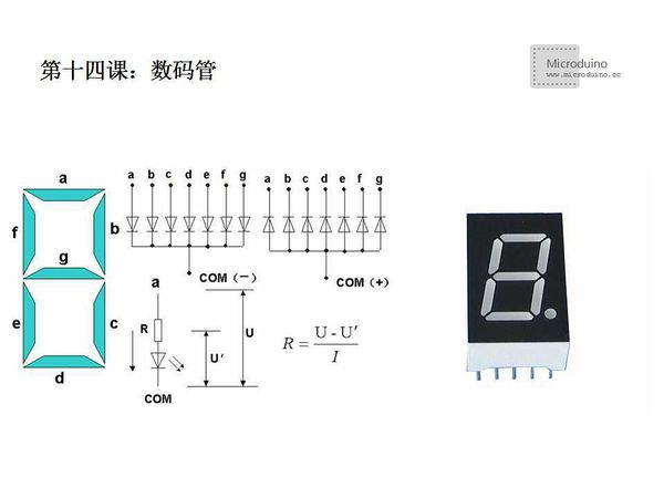
Brief Introduction: LED Segment Displays comprises multiple leds which encapsulate together to "8" type, the connection was made in inside, Only lead to their each stroke, common electrode. These segments are respectived by the letters a, b, c, d, e, f, g, dp. After the digital tube has powered on specific segment, the specific segment will shine, such as: to display number "2", should bright on a, b, g, e, d, and c, f,dp doesn't bright. LED digital tube is usually devided into bright and super bright two types, also have different size 0.5 inch, 1 inch, etc. Small size commonly uses one light-emitting diode, and the big size of the digital tube is composed of two or more light-emitting diodes. In general, the pressure drop of a single light emitting diode is about 1.8 V, the electric current shall not exceed 30mA. Light emitting diode connectes the anode together and then connected to the power of positive is called common anode digital tube, light emitting diode connected to the cathode and then connected to the power of the cathode is called common cathode digital tube. LED digital tube commonly use to display numbers and characters, including 0, 1, 2, 3, 4, 5, 6, 7, 8, 9, A, B, C, D, E, F. Measure Pin: LED digital tube is an often used component, but no unified naming method for many models which causes a lot of confusion to some beginners. In fact, LED digital tube is put multiple LED light-emitting diodes(leds) together, and it's not a high tech. An LED is called one segment. Common cathode and common anode: LED digital has common anode and common cathode two types, connect the anode of LED light-emitting diodes togeter (usually a figure 8 and a decimal point) as a pin, called common anode, on the contrary, is called common cathode. When used, connect these pin to VCC or GND. Put more of these eight words together again, that is a number of digital tube.Very simple. Find common cathode and common anode: Firstly, we find a power supply (3 to 5 v) and 1kΩ (or hundreds of ohm) resistor, VCC concatenated a resistor amd GND connect to arbitrary two pin, there are a lot of combinations, but there is always a LED light, find one is enough, then keep GND connection, VCC one by one touch the left pin, if there are multiple leds (usually 8), that is common cathode. Instead keep VCC connection, GND one by one touch the left foot, if there are multiple leds (usually 8), that is common cnode.
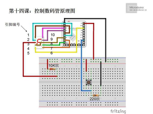
SchematicNote: 1. Connect digital tube's a~g segment to Microduino's D0~D6 pins. If you don't know the segment, you can power on it to identify a ~ g. 2. Identify common cathode and common anode. For common cathode, connect a 220Ω resistor to power supply cathode. For common cnode, connect a 220Ω resistor to power +5v。3. 220Ω电阻视数码管实际工作亮度与手头现有原件而定,不一定需要准确。 ProgramDownload program: https://github.com/Microduino/Microduino_Tutorials/tree/master/Microduino_Advanced/MicroduinoDigitalShowPoint /*
Arduino single digital tube dice
Ansifa 2011-12-28
*/
//Define the segment code, ten elements generated by LED code generator, use common cnode
int a[10] = {0xC0, 0xF9, 0xA4, 0xB0, 0x99, 0x92, 0x82, 0xF8, 0x80, 0x90};
void setup()
{
DDRD = 0xFF; // AVR defines the low seven bits of as output, that is 0xFF=B11111111 corresponding to D7~D0
pinMode(12, INPUT); //D12 used as the dice pause swtich
}
void loop()
{
for(int i = 0; i < 10; i++)
{
//Output the segment code to low 7 bits of PortD, that are Arduino pin D0~D6. This need to D7 state and add to segment code, then output.
PORTD = a[i];
delay(50); //Delay 50ms
while(digitalRead(12)) {} //If D12 is high level, then in dead loop, stop LED
}
}
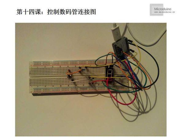
DebugStep 1:Cope the code to IDE and compile it. In source only, used some AVR code. PORTD is the port output grammar in AVR. 8 bits correspondign to D7~D0, PORTD=00001001 that is D3, D0 is high level. PORTD = a, that means find the correspondign segment code and output to D7~D0. DDRD as an AVR grammar can control pin as input/output. DDRD = 0xFF, thta means D0~D7 as output pin. Step 2:Set up circuit, as follows: Step 3:Run program ResultDigital tube will display from 0 to 9 fastly, press the switch to stop then you get a number, used as a dice. Video |


