“震动传感器”的版本间的差异
(add) |
853387039@qq.com(讨论 | 贡献) |
||
| 第3行: | 第3行: | ||
|- | |- | ||
| | | | ||
| − | == | + | ==概述== |
| − | + | 震动传感器,内部结构相当于一个金属球固定在一个特殊的弹簧上作为一极,它的周围是另外一极,振动达到一定的幅度后两极接通,从而判断发生震动。震动传感器输出数字信号。 | |
| − | + | <br /> | |
| − | |||
| − | |||
| − | |||
| − | |||
| − | |||
| − | |||
| + | ==规格== | ||
| + | *电器规格 | ||
| + | **工作电压:5V | ||
| + | **输入设备 | ||
| + | *技术参数 | ||
| + | **极宽的震动侦测范围. | ||
| + | **无方向限制 | ||
| + | **60,000,000次震动保证 (接脚表面特别镀金) | ||
| + | *尺寸 | ||
| + | **传感器大小:9.0mm*9.15mm | ||
| + | **板子大小:20mm*20mm | ||
| + | **1.27mm间距的4Pin接口与sensorhub相连 | ||
| + | *接法 | ||
| + | **引脚说明:GND、VCC、信号输入、NC(空)。 | ||
| + | **数字输入 | ||
| + | ==开发== | ||
| + | ===设备=== | ||
| + | *'''[[mCookie-CoreUSB/zh]]''' | ||
| + | *'''[[mCookie-Hub/zh]]''' | ||
| + | *'''[[Microduino-Shake/zh]]''' | ||
*其他硬件设备 | *其他硬件设备 | ||
**USB数据连接线 一根 | **USB数据连接线 一根 | ||
| + | [[File:shock-module.jpg|center|600px]] | ||
| + | ===准备=== | ||
| + | *Setup 1:将shock传感器接口和Hub的数字口(D6)接起来。 | ||
| + | [[file:mCookie-shock-sensor.JPG|600px|center]] | ||
| + | *Setup 2:将CoreUSB,Hub,shock连接在一起。通过USB数据线将接入电脑。 | ||
| + | [[file:mCookie-shock-pc.JPG|600px|center]] | ||
| + | ===调试=== | ||
| + | *打开Arduino IDE,将下列代码复制到IDE中。 | ||
| + | <source lang="cpp"> | ||
| + | #define pushButton 6 | ||
| − | + | int buttonState; | |
| − | |||
| − | |||
| − | |||
| − | |||
| − | |||
| − | |||
| − | |||
| − | |||
| − | |||
| − | |||
| − | |||
| − | |||
| − | |||
| − | |||
| − | |||
| − | |||
| − | |||
| − | |||
| − | |||
| − | |||
| − | |||
| − | |||
| − | |||
| − | + | // the setup routine runs once when you press reset: | |
| + | void setup() { | ||
| + | // initialize serial communication at 9600 bits per second: | ||
| + | Serial.begin(9600); | ||
| + | // make the pushbutton's pin an input: | ||
| + | pinMode(pushButton, INPUT); | ||
| + | } | ||
| − | + | // the loop routine runs over and over again forever: | |
| + | void loop() { | ||
| + | // read the input pin: | ||
| + | buttonState = digitalRead(pushButton);//读取震动传感器输入的值 | ||
| + | // print out the state of the button: | ||
| + | Serial.print("buttonState:"); | ||
| + | Serial.println(buttonState); //串口打印震动传感器的值 | ||
| + | delay(100); //延时100ms | ||
| + | } | ||
| + | </source> | ||
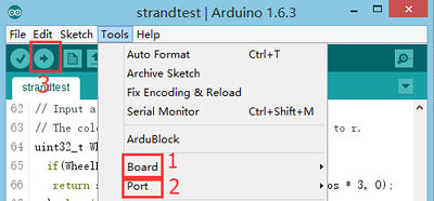
| + | *选择正确的板卡和COM端口,编译通过后直接下载。 | ||
| + | [[file:upload.JPG|400px|center]] | ||
| + | *打开串口监视器。 | ||
| + | [[file:comxx.JPG|400px|center]] | ||
| + | *可以禁止不动时“buttonState”的值为0,震动时的值为1; | ||
| + | [[file:Crash-one-res.JPG|400px|center]] | ||
| + | '''*采用“digitalRead(XX)”函数来读取震动信号,该信号为数字信号,只有“0”和“1”两种状态。''' | ||
| + | ==应用== | ||
| + | *防盗器 | ||
==视频== | ==视频== | ||
|} | |} | ||
2015年10月27日 (二) 04:58的版本
概述震动传感器,内部结构相当于一个金属球固定在一个特殊的弹簧上作为一极,它的周围是另外一极,振动达到一定的幅度后两极接通,从而判断发生震动。震动传感器输出数字信号。
规格
开发设备
准备
调试
#define pushButton  6

int buttonState;

// the setup routine runs once when you press reset:
void setup() {
  // initialize serial communication at 9600 bits per second:
  Serial.begin(9600);
  // make the pushbutton's pin an input:
  pinMode(pushButton, INPUT);
}

// the loop routine runs over and over again forever:
void loop() {
  // read the input pin:
  buttonState = digitalRead(pushButton);//读取震动传感器输入的值
  // print out the state of the button:
  Serial.print("buttonState:");
  Serial.println(buttonState);  //串口打印震动传感器的值
  delay(100);     //延时100ms
}
*采用“digitalRead(XX)”函数来读取震动信号,该信号为数字信号,只有“0”和“1”两种状态。 应用
视频 |
