“单色点阵-BMP图”的版本间的差异
(创建页面,内容为“{| style="width: 800px;" |- | <p style="color: #4F4E4E;font-size:220%">'''单色点阵-BMP图'''</p> <br> 在下面的示例中,使用Core核心通过IIC控制单...”) |
|||
| 第13行: | 第13行: | ||
*[[Sensor-Dot_Matrix-S2/zh|Sensor-Dot_Matrix-S2]] | *[[Sensor-Dot_Matrix-S2/zh|Sensor-Dot_Matrix-S2]] | ||
<br> | <br> | ||
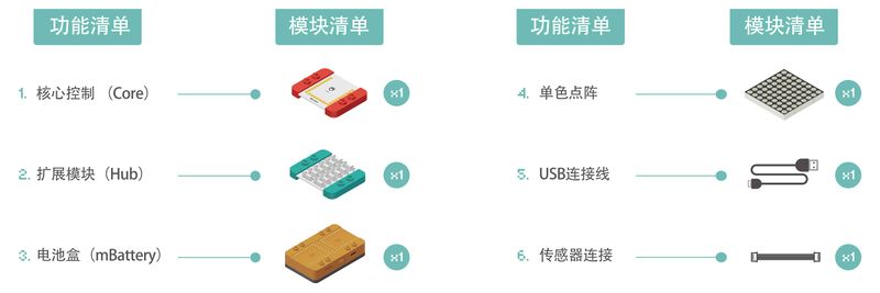
| − | [[File:Sensor_Dot_Matrix-S2_module.jpg| | + | [[File:Sensor_Dot_Matrix-S2_module.jpg|800px|center]] |
<br> | <br> | ||
<br> | <br> | ||
| 第21行: | 第21行: | ||
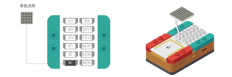
将Battery、Core、Hub堆叠在一起,通过MicroUSB数据线接入电脑。初次使用请参考:[[AVR核心:Getting_started/zh|Getting Started]]。 | 将Battery、Core、Hub堆叠在一起,通过MicroUSB数据线接入电脑。初次使用请参考:[[AVR核心:Getting_started/zh|Getting Started]]。 | ||
<br> | <br> | ||
| − | [[File:Sensor_Dot_Matrix-S2_circuit.jpg| | + | [[File:Sensor_Dot_Matrix-S2_circuit.jpg|800px|center]] |
<br> | <br> | ||
<br> | <br> | ||
2018年5月16日 (三) 09:08的版本
|
单色点阵-BMP图
所需硬件
电路搭建 将彩色点阵任意接口接到Hub的IIC引脚。
代码
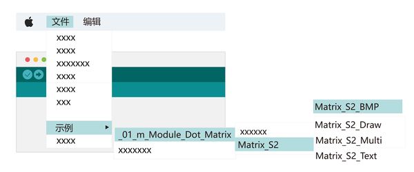
相关案例 |


