Digital Tube Control
ObjectiveThe course will show you how to use Processing to control a common cathode digital tube. Equipment
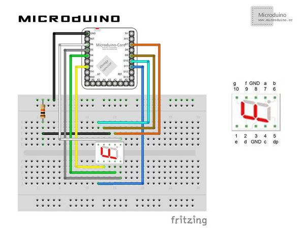
SchematicProgramDebuggingStep 1:Build the hardware environment according to the schematic, just like this:
The code the two ends(Processing and Microduino) Microduino: Using Firmata's StandardFirmata program. Processing: //Define eight led lights to indicate a digital tube. LED[] leds = new LED[8]; // An array of 8 led objects! //Define Microduino pins of the corresponding digital tube pins (1,2...10). int microduinoPins[] = {//Correspondence microduino pin for 7 segment
11,2,4,5,6,7,9,10};
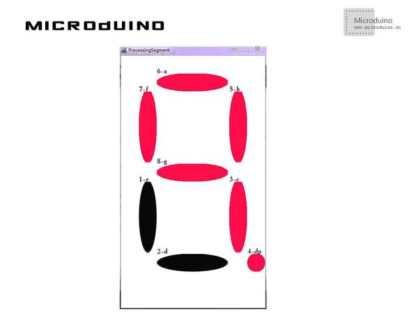
//Define the name of each segment LED digital tube String segmentLables[]={"1-e","2-d","3-c","4-dp","5-b","6-a","7-f","8-g"};
 for (int i = 0; i < leds.length; i ++ ) { // Initialize each led and output pin using a for loop.
   arduino.pinMode(microduinoPins[i], Arduino.OUTPUT);
 }

 leds[0] = new LED(50, 350, 50,200,1);
 leds[1] = new LED(100, 550, 200,50,2);
 leds[2] = new LED(300, 350, 50,200,3);
 leds[3] = new LED(350, 550, 50,50,4);
 leds[4] = new LED(300, 100, 50,200,5);
 leds[5] = new LED(100, 50, 200,50,6);
 leds[6] = new LED(50, 100, 50,200,7);
 leds[7] = new LED(100, 300, 200,50,8);
//Draw the digital tube in draw(), judge the status of the led lights, and send the current status to Microduino for (int i = 0; i < leds.length; i ++ ) { // Run each Car using a for loop.
leds[i].display();
//draw segemnt lables
text (segmentLables[i], leds[i].xpos, leds[i].ypos);
if (leds[i].button) {//switch led on/off
arduino.digitalWrite(microduinoPins[i], Arduino.HIGH);
}
else {
arduino.digitalWrite(microduinoPins[i], Arduino.LOW);
}
}
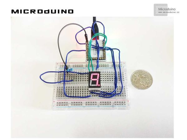
Step 3:Download the code and get it compiled successfully. Step 4:There will appear eight led lights in Processing after the system goes smoothly. Please click each led and see the response of the digital tube. ResultClick the mouse and the corresponding digital tube led will turn on or off, as follows: Video |


