1장. LED 켜기(브레드보드를 이용하기)
| Language | English |
|---|
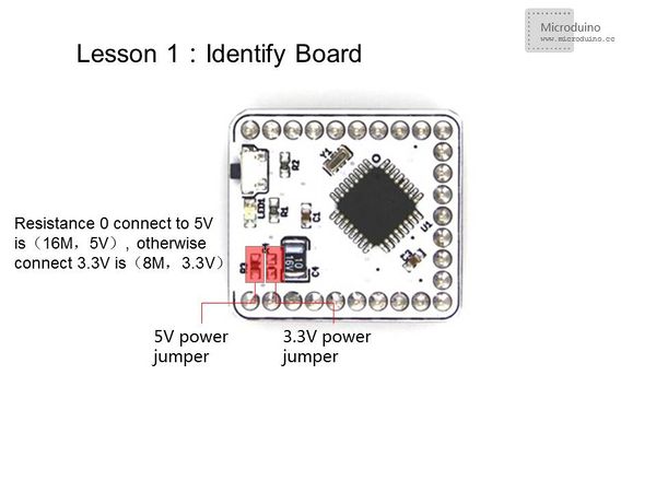
목표마이크로두이노를 이용하여 LED를 제어하는 방법을 배우게 될 것입니다.. 마이크로아두이노의 I/O 포트를 어떻게 제어하는지 배울 것이고 I/O 포트를 제어하는 것은 매우 기초적인 기술이며 앞으로도 많이 사용하게 될 것입니다. 재료마이크로아두이노 코어모듈은 아트멜사의 ATmega328P, ATmega168PA 시리즈를 기반으로 만들어진 8비트 마이크로프로세서 개발보드입니다. 자세한 사항은 마이크로두이노 코어모듈을 참조하세요 마이크로두이노 코어 또는 코어 플러스 모듈과 PC를 연결하여 프로그램을 다운로드할때 사용하는 모듈입니다. 마이크로 USB 사양을 채택하고 있습니다. 1달러 동전과 비슷한 사이즈를 가지고 있습니다. 스마트폰의 USB 케이블과 같으므로 편리하고 실용적입니다. 자세한 사항은 Microduino-FT232R를 참조하세요.
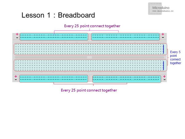
브레드보드 알아보기In the vertical direction,5 points connected together and 25 points connected together in a horizontal direction. Some bread has 50 points connected together, so make sure connection format before you use it, in order to avoid generating erroneous results. The next two rows of points 50 have more usage, one row as GDN, the other row as VCC. Please refer to the following picture. 저항과 LEDLimiting resistor is used to prevent LED burned. Usually red and green LED voltage is 1.8 ~ 2.4V, blue and white is 2.8 ~ 4.2V, 3mmLED rated current is 1 ~ 10mA, 5mmLED rated current is 5 ~ 25mA, and 10mmLED rated current is 25 ~ 100mA. According to R = U / I to the calculated resistance. Usually hundreds of ohm should be ok. 회로도There are two connection methods, one is that led cathode connects to GND, anode connects to Microduino digital I/O port 13, which is the high light led. The other method ist that led cathode connected Microduino digital I/O port 13, anode connects to VCC, so that low-level light led.
프로그램
int led = 13;// Define the PIN
void setup() {
  pinMode(led, OUTPUT);  // Define the I/O port 13 as output
}
void loop() {
digitalWrite(led, HIGH); //I/O port 13 output High. If the connection is high lighted,the LED will light, otherwise extinguished
delay(1000);               // delay 1s
digitalWrite(led, LOW); //I/O port 13 output Low.If the connection is high lighted,the LED off, otherwise light.
delay(1000);               // delay 1s
}
int ledPin=13;
#define TIME 1000
long time1=0,time2=0;
void setup()
{
  pinMode(ledPin,OUTPUT);
}
void loop()
{
if(millis()<time2+TIME)
{
digitalWrite(ledPin,HIGH);
time1=millis();
}
else
{
digitalWrite(ledPin,LOW);
if(millis()>time1+TIME)
time2=millis();
}
}
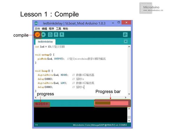
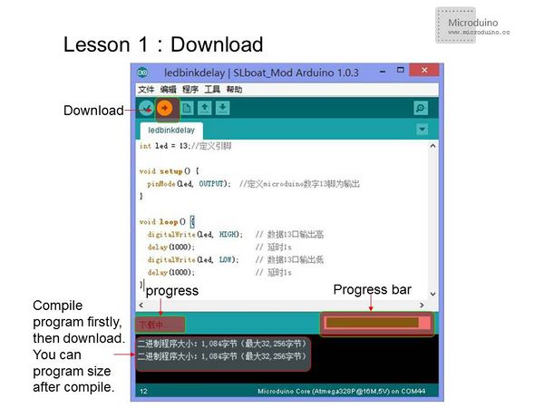
Using function millis () is better than the delay () function, less resource and fewer delays on the system. 프로그램 다운로드 방법
결과After the download, you can see LED flashes once every 1s. 비디오 |


