|
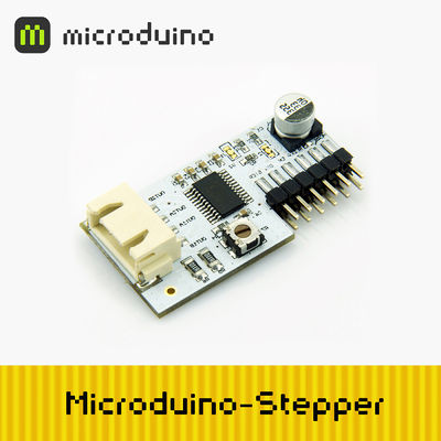
Microduino-Stepper is a DMOS micro-step drive with a converter and overcurrent protection. It can be used to operate bipolar steepper motors in full, half,1/4,1/8 and 1/16 step model.Widely used in control system.
|
Feature
- Easily to control;
- Four optional stepping modes:full, 1/2,1/4 and 1/16
- Perfect protection mechanisms:
- Overtemperature shutdown circuit, undervoltage lockout, crossover current protection;
- Ground short circuit protection, load short-circuit protection;
- Use potentiometer to adjust the current;
- Automatic current decay mode detection / selection;
- Compliance with smoke-free fire (NSNF) specification (ET package);
- The unique plug way and more space savings.
|
Specifications
- Support bipolar stepper motor;
- Just input a pulse for the "STEP", it will drives the motor to produce micro-step. Without the need for phase sequence tables, high frequency control lines, or complex interfaces to program;
- The maximum output current can be adjusted via potentiometer, resulting in higher step rate;
- Four optional stepping modes:
Electrical Specifications
- VCC voltage:
- VMOT voltage:
- Maximum operating current:
- Under the Low current sleep mode, the current less than 10uA;
- Automatic current decay mode detection/selection;
- Overtemperature shutdown circuit, undervoltage lockout, crossover current protection;
- Ground short circuit protection, load short-circuit protection;
Pin Description
| Microduino Stepper Pin |
Microduino Pin |
function
|
| STEP |
Microduino IO port |
Pulse drives the stepper motor produces micro-stepping
|
| DIR |
Microduino IO port |
Control the rotation direction of the stepper motor
|
| EN |
Microduino IO port |
Open or close the drive (active low)
|
| VMOT |
External power source |
External power supply to the stepper motor
|
| VCC |
VCC |
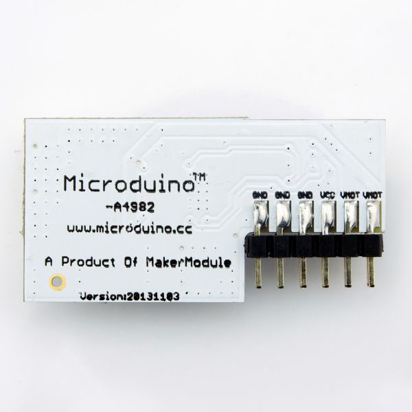
power to A4982 and Microduino
|
| GND |
GND |
Common GND
|
|
Document
Eagle PCB 文件:Microduino-A4982.zip
Main component
Development
Arduino library and support package
Stepper motor wiring
- Stepper motor connects with Microduino Stepper:
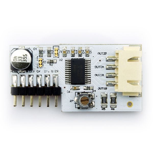
- Four-wire two-phase stepper motor has two sets of coils a, b, the coil resistance is very small, only several ohms. a and b are totally insulated from the group, not communicating. Measured with a multimeter, connectivity is a set;
- After measured out, a set of coils connect to OUT1A, OUT1B, another coil connects to OUT2A, OUT2B.
- By changing the MS1 & MS2 to change the stepping mode (Microduino A4982 default is 1/16 step mode);
Application
Program download
Testing Program:文件:Program Test A4982.zip
Stepper Simple Application
- Connect the Micorduino core module,Microduino A4982 and the stepper motor.
- Prepared hardware:Microduino FT232R、Microduino Core、Microduino A4982、Four-wire two-phase stepper motor、9V~12V power;
- Prepared software:Microduino provides testing program(Arduino part)、Arduino IDE(1.0 release upper)、AccelStepper library,
- Put the downloaded library to the libraries folder of the Arduino IDE installation folder;
- Strat Ardino IDE, open the testing program, card type chooses “Microduino Core (Atmega328P@16M,5V)”, download directly;
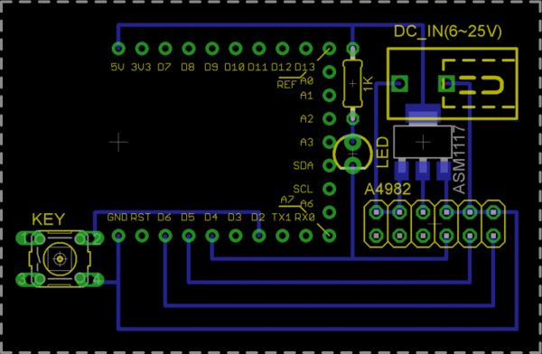
- Use the pegboard setting up the circuit: (blue line at the bottom),as following picture:
- Microduino Stepper drives a stepper motor:[ Test_A4982]
- External 9V or 12V power supply, the motor does not rotate in initialization state;
- Press the button, the stepper motor begins to rotate as setting speed, and LED indicator lights, reverse rotation after a few laps, the cycle repeated;
- Press the button again to close the drive, LED indicator lights off. Key detection through an interrupt, turn the switch driver.
Pictures
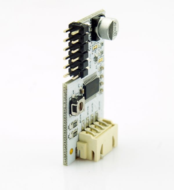 Microduino A4982 Erection |
|
|
