Microduino-Core

来自Microduino Wikipedia
Makermodule讨论 | 贡献2013年12月15日 (日) 09:34的版本
跳转至: 导航搜索
Microduino-Core

Microduino-Core is one of core modules of Microduino series, Microduino-Core

is an open source hardware and Arduino Uno compatible. It is an 8-bit microcontroller development

board, based on Atmel ATmega328P/ATmega168PA series.

Comparing to Arduino Uno, Microduino-Core is featured by:

Microduino-Core and Microduino-FT232R modules -- MCU and USB2TTL parts. it

means once designers uploaded program into Microduino-Core, Microduino-FT232R

will be not necessary anymore, designers could have many Microduino-Core/Core+ modules with only

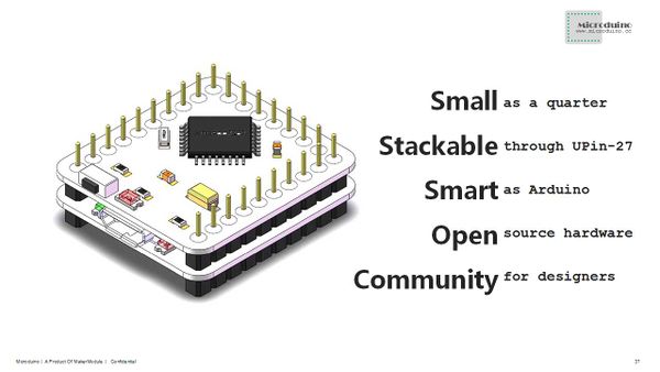
one Microduino-FT232R. The board size becomes very small as only 25.4mm X 27.94mm

(1.0inch X 1.1inch), like a quarter.

  • Microduino series uses the U-Shape 27-pin interface (UPin-27), the standard interface of

Microduino, all Microduino modules and sensors can be easily stacked and extended, it is delivered

ready to plug in.

  • With tiny shape and uniform interface, Microduino series dramatically decreases the size and

cost of design prototype, remarkable improves usability and flexibility of Arduino-compatible

boards, as well as user experience.


Microduino uses the same development environment as Arduino IDE, designers can use the Arduino

IDE, Processing on Microduino for idea realization, prototype development and low volume

production.

Microduino uses optiboot for bootloader, it takes less Flash than Arduino default engine and

optimizes program uploading.

Currently, there are 4 different configurations for Microduino-Core modules:

Type Flash SRAM EEPROM Frequency Supply
Atmega328P@16M,5V 32K 2K 1K 16M 5.0V
ATmega328P@8M,3V3 32K 2K 1K 8M 3.3V
ATmega168PA@16M,5V 16K 1K 512 16M 5.0V
ATmega168PA@8M,3V3 16K 1K 512 8M 3.3V

Different configurations in frequency and supply voltage:

  • Clock frequency and supply voltage are paired, 8M module is supplied by 3.3V voltage, while 16M

module is by 5.0V voltage.

  • A 16M with 5V Microduino-Core module is recommended for desktop equipments or designs;

regarding mobile equipments or designs, a 8M with 3.3V module is suggested for low power and

battery supply purposes.


Core vs Core+

applications which require large SRAM/EEPROM/Flash and more I/O ports.

standard module interface of Microduino series. The main difference between them is MCU chip: -

Core module uses ATmega328P/ATmega168PA, as same as Arduino Uno; -Core+ module uses

ATmega644PA/ATmega1284P, its performance is similar to Arduino Mega2560.

Microduino Chip Flash SRAM EEPROM Digital I/O Analog I/O PWM Hardware Serial
Core Atmega168PA 16K 1K 512 23 8 6 1
ATmega328P 32K 2K 1K 23 8 6 1
Core+ Atmega644PA 64K 4K 2K 32 8 6 2
ATmega1284P 128K 16K 4K 32 8 6 2
  • According above table, Core and Core+ are different in Flash, EEPROM and SRAM size, also, they

supply different size of digital I/O and hardware serial ports, and there are 10 more digital I/O

and 1 more hardware serial ports in Core+. Designers can select specific module regarding

different application requirements on function, performance and power.

  • Both Core and Core+ use UPin-27 interface, Microduino program can be smoothly ported between

them.

Features

  • Small, Stack, Strong
  • Open source hardware, using the same development environment as Arduino IDE
  • Microduino-Core can be burned with ISP, same as Arduino, easy "bootloader"
  • Using the U-Shape 27-pin interface (UPin-27), the standard interface of Microduino, all

Microduino modules and sensors can be easily stacked and extended through it

  • Delivered ready to plug in.
  • 2.54mm (0.1 inch) pin pitch, compatible to bread board and hole board

Specifications

  • Microcontroller: ATmega328P/ATmega168PA
  • Operating Voltage: 5V/3.3V
  • Input Voltage (limits): 6-20V
  • Digital I/O Pins: 14 (of which 6 provide PWM output with D3,D5,D6,D9,D10 and D11)
  • Analog Input Pins: 8 (2 more comparing to Arduino Uno)
  • DC Current per I/O Pin: 40 mA
  • DC Current: 50 mA
  • Serial: 0 (RX) and 1 (TX). Used to receive (RX) and transmit (TX) TTL serial data.
  • External Interrupts: 2 and 3. These pins can be configured to trigger an interrupt on a low

value, a rising or falling edge, or a change in value. See the attachInterrupt() function for

details.

  • PWM: 3, 5, 6, 9, 10, and 11. Provide 8-bit PWM output with the analogWrite() function.
  • SPI: 10 (SS), 11 (MOSI), 12 (MISO), 13 (SCK). These pins support SPI communication using the SPI

library.

  • TWI: A4 or SDA pin and A5 or SCL pin. Support TWI communication using the Wire library.
  • AREF. Reference voltage for the analog inputs. Used with analogReference().
  • Flash Memory 32 KB (ATmega328P) of which 0.5 KB used by bootloader
  • SRAM 2 KB (ATmega328P)
  • EEPROM 1 KB (ATmega328P)
  • Clock Speed 16MHz(5V) / 8Mhz(3.3V)
  • Currently, there are 4 different configurations for Microduino-Core modules:
Type Flash SRAM EEPROM Frequecy Supply
Atmega328P@16M,5V 32K 2K 1K 16M 5.0V
ATmega328P@8M,3V3 32K 2K 1K 8M 3.3V
ATmega168PA@16M,5V 16K 1K 512 16M 5.0V
ATmega168PA@8M,3V3 16K 1K 512 8M 3.3V
文件:Microduino-Core-Pinout1.png
Microduino-Core-Pinout
文件:Microduino-Core-Pinout2.png
Microduino-Core-Pinout
文件:Microduino-Core-Pinout3.png
Microduino-Core-Pinout
文件:Microduino-Core-Pinout.png
Microduino-Core-Pinout


download

Documents

文件:Microduino-Core-SCH.png
Microduino-Core Schematic


文件:Microduino-Core-PCB.png
Microduino-Core PCB


Development

  • Microduino Arduino IDE Configuration
    • 1. Install Arduino IDE: Microduino use the same IDE as Arduino, please download Arduino IDE

from 【Arduino IDE official】 and install it in your

disk. (if you already have it, just skip this step). Please check Arduino IDE details from

Reference】 and

Workshop】.

    • 2. Patch Microduino package: Please download Microduino package for Arduino IDE from

download】, and unzip is to {Your Arduino Install

Driectory}/hardware directory.

    • Microduino Arduino IDE Reference workshop: 【Arduino IDE Microduino Configuration】.
    • 3. Programming: To upload program to Microduino-Core/Core+ through Arduino IDE, designers are

recommended to use Microduino-FT232R module.

    • 4. Enjoy your Microduino journey!
  • Burn Microduino BootLoader
    • Bootloader burning is necessary if designers want to update Microduino-Core/Core+ firmware by

themselves, designers can leaverage Arduino Uno or another burned Microduino-Core/Core+ to make a

new one.

    • Microduino bootloader workshop: 【[[Burn Bootloader to Microduino-Core/Core+ with an

Arduino]]】.

    • Bootloader is specified for different Microduino-Core/Core+ configurations, correct one must be

selected during burning.

    • Initial bootloader is designed for ATmegaX8 series optiboot, which occupies only 512 bytes

flash.

Applications

  • room-Microduino
  • obdii-Microduino
  • pilot-Microduino
  • green-Microduino
  • music-Microduino

Buy

History

  • 2012/12/16: Published Microduino-Core patch for Arduino IDE
  • 2012/11/18: Optimized the first formal release, finalized Miroduino-Core configuration
  • 2012/11/06: Beta version.

Pictures

文件:Microduino-Core-F.JPG
Microduino-core Front


文件:Microduino-Core-B.JPG
Microduino-core Back


Microduino-core 3D model