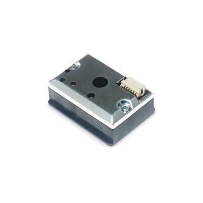
Microduino-Dust
1304410487@qq.com(讨论 | 贡献)2015年10月29日 (四) 03:50的版本 (Created page with "{{Language|Microduino-Dust}} {| style="width: 800px;" |- | 400px|thumb|center| Microduino-Dust Microduino-Dust is a PM2.5 sensor. ==Features== ...")
| Language | English |
|---|
|
Microduino-Dust is a PM2.5 sensor. 目录Features
Specification
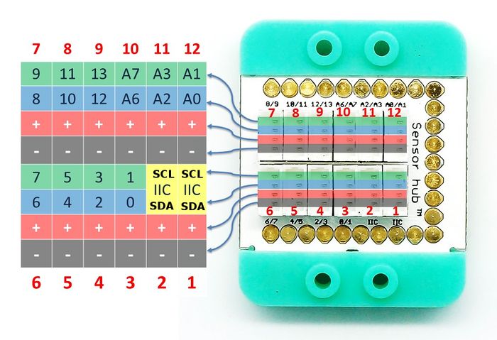
You can use Microduino-IO-Split to divide the two signals, by connecting the interface of Microduino-Dust with the IN interface of Microduino-IO-Split: The IO-Split's A-OUT interface can be connected to the pin (10, 11 or 12) of the Sensorhub with the corresponding pin (A6,A2 or A0); The IO-Split's B-OUT interface can be connected to the pin (3~10) of the Sensorhub with the corresponding pin (D0,D2,D4,D6,D8,D10,D12). Document
DevelopmentMicroduino-Dust can be applied in outdoor air quality detection or indoor dust detection. Application
#define FAN_PIN 10      //Fan control pin
#define LED_PIN 12      //Sensor LED control pin
#define DUST_PIN A0     //Sensor detection
#define TIME1 280
#define TIME2 40
#define TIME3 9680

int dustVal = 0;
float dustVoltage = 0;
float dustDensity = 0;

void setup(){
  Serial.begin(9600);
  pinMode(FAN_PIN, OUTPUT);
  pinMode(LED_PIN, OUTPUT);
  digitalWrite(FAN_PIN, LOW);
}

void loop(){
  digitalWrite(FAN_PIN, HIGH);    //Open the fan before detecting
  delay(3000);
  digitalWrite(FAN_PIN, LOW);     //Close the fan after 3s delay
  digitalWrite(LED_PIN,LOW);      //Turn on LED inside the sensor
  delayMicroseconds(TIME1);       //Wait for 280us
  dustVal = analogRead(DUST_PIN); //Analog value sampling
  delayMicroseconds(TIME2);       // Wait for 40us
  digitalWrite(LED_PIN,HIGH);     //Turn off the LED
  delayMicroseconds(TIME3);
  dustVoltage = dustVal * (5.0/1024.0);    //Convert the analog value to voltage value.
  dustDensity = 0.17 * dustVoltage - 0.1;  //Convert the voltage value to dust density (Output unit: mg / m³)
  Serial.println(dustDensity);
  delay(1000);
}
PurchaseHistoryPictures
文件:Microduino-Dust-F.JPG Microduino-Dust Front
文件:Microduino-Dust -b.JPG Microduino-Dust Back |

