MCookie-Motor
1304410487@qq.com(讨论 | 贡献)2015年10月15日 (四) 02:27的版本 (Created page with "{{Language|mCookie-Motor}} {| style="width: 800px;" |- | 400px|thumb|right|mCookie-Motor mCookie-Motor is a DC motor controller with PWM(Pulse W...")
| Language | English |
|---|
|
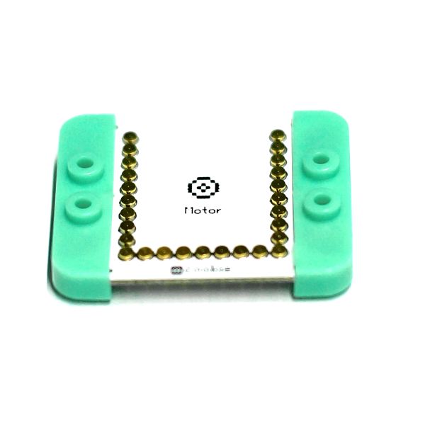
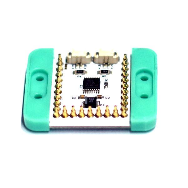
文件:Motor-motor-rect.jpg mCookie-Motor mCookie-Motor is a DC motor controller with PWM(Pulse Width Modulation). The speed of the motor can be controlled through PWM and mCookie-Motor has to be powered with BM module.
目录[隐藏]Features
Specification
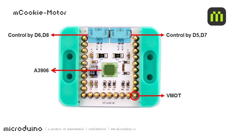
Note: The pins including 5, 6, 7 and 8 cannot be occupied by other sensors while using the Motor or it may cause problems. 文件:Motor-Pinout-2Big.jpg 800px DocumentDevelopmentDC Motor Wire Connection
//(D6, D8) controls motor (1A, 1B)
#define OUT1A 6
#define OUT1B 8
//(D5, D7) controls motor (2A, 2B)
#define OUT2A 5
#define OUT2B 7
PWM Rate ControlProject
#define OUT1A 6
#define OUT1B 8
#define OUT2A 5
#define OUT2B 7

void setup()
{
  pinMode(OUT1A, OUTPUT);
  pinMode(OUT1B, OUTPUT);
  pinMode(OUT2A, OUTPUT);
  pinMode(OUT2B, OUTPUT);
}

void loop()
{
head();
delay(2000);
back();
delay(1000);
stop();
delay(500);
}

void head()
{
  digitalWrite(OUT1A, HIGH);
  digitalWrite(OUT1B, LOW);
  digitalWrite(OUT2A, HIGH);
  digitalWrite(OUT2B, LOW);
}
void back()
{
  digitalWrite(OUT1A, LOW);
  digitalWrite(OUT1B, HIGH);
  digitalWrite(OUT2A, LOW);
  digitalWrite(OUT2B, HIGH);
}
void stop()
{
  digitalWrite(OUT1A, LOW);
  digitalWrite(OUT1B, LOW);
  digitalWrite(OUT2A, LOW);
  digitalWrite(OUT2B, LOW);
}
//(D6, D8) controls motor (1A, 1B)
#define OUT1A 6
#define OUT1B 8
//(D5, D7) controls motor (2A, 2B)
#define OUT2A 5
#define OUT2B 7

void setup()
{
  pinMode(OUT1A, OUTPUT);
  pinMode(OUT1B, OUTPUT);
  pinMode(OUT2A, OUTPUT);
  pinMode(OUT2B, OUTPUT);
}

void loop()
{
  for (int fadeValue = 0; fadeValue <= 255; fadeValue += 5)
    //Loop statement. Along with PWM rate increases, you can change brightness level by controlling fadeValue.
  {
    analogWrite(OUT1A, fadeValue);  //Write rate level into the motor
    digitalWrite(OUT1B, LOW);
    analogWrite(OUT2A, fadeValue);
    digitalWrite(OUT2B, LOW);
    delay(100);                       //Delay time of rate. (The unit is ms)
  }
  for (int fadeValue = 255; fadeValue >= 0; fadeValue -= 5)
    // Loop statement. Along with PWM rate decreases, you can change brightness level by controlling fadeValue.
  {
    digitalWrite(OUT1A, LOW);
    analogWrite(OUT1B, fadeValue);  // Write rate level into the motor
    digitalWrite(OUT2A, LOW);
    analogWrite(OUT2B, fadeValue);
    delay(100);                     // Delay time of rate. (The unit is ms)
  }
  delay(1000);
}
Other Projects: PurchaseHistoryPicturesVideo |


