“蓝牙彩灯”的版本间的差异
853387039@qq.com(讨论 | 贡献) (→设备) |
853387039@qq.com(讨论 | 贡献) (→搭建硬件) |
||
| 第36行: | 第36行: | ||
APP下载:'''[[File:Microduino-LAMP-APP.zip]]'' | APP下载:'''[[File:Microduino-LAMP-APP.zip]]'' | ||
| − | == | + | ==准备== |
| − | *Setup | + | *Setup 1:用USB线将CoreUSB模块与PC/Mac相连,并打开Arduino IDE。 |
| − | [[File: | + | [[File:CoreUSB_Ble_pc.jpg|600px|center|thumb]] |
| − | *Setup | + | *Setup 2:点击Files > Examples > mCookie > _103_BLE_Light, 加载程序。或者下载: |
| − | [[ | + | [[File:_103_BLE_Light.jpg|600px|center|thumb]] |
| − | [[File: | + | |
| + | ==程序说明== | ||
| + | *蓝牙使用的是串口通讯,对于mCookie-CoreUSB来说,使用的是'''Serial1''',因此定义了串口服务。 | ||
| + | <source lang="cpp"> | ||
| + | #define my_Serial Serial1 | ||
| + | </source> | ||
| + | *同时,蓝牙通讯的波特率(速度)为:9600,需要在'''setup()'''里面定义了串口通讯速率。 | ||
| + | <source lang="cpp"> | ||
| + | my_Serial.begin(9600); | ||
| + | </source> | ||
| + | *彩灯控制说明 | ||
| + | <source lang="cpp"> | ||
| + | #define PIXEL_PIN A0 // Digital IO pin connected to the NeoPixels. | ||
| + | #define PIXEL_COUNT 6 | ||
| + | |||
| + | Adafruit_NeoPixel strip = Adafruit_NeoPixel(PIXEL_COUNT, PIXEL_PIN, NEO_GRB + NEO_KHZ800); | ||
| + | </source> | ||
| + | **'''PIXEL_PIN''':彩灯的控制引脚,用户可以自己更改控制引脚,同时也要更改硬件连接。 | ||
| + | **'''PIXEL_COUNT''':控制灯的个数,蓝牙控制最多可以控制6个,因为App蓝牙传输数据最多写了6个。 | ||
| + | *“#define xxx yy”函数:把“yy”的值赋予给“xxx”,上面函数也可以改成: | ||
| + | <source lang="cpp"> | ||
| + | Adafruit_NeoPixel strip = Adafruit_NeoPixel(6, A0, NEO_GRB + NEO_KHZ800); | ||
| + | </source> | ||
| + | *“ble()”函数是用来接收并解析手机发送的数据,解析数据函数: | ||
| + | <source lang="cpp"> | ||
| + | sscanf((char *)strstr((char *)buffer, "C:"), "C:%d,%d,%d,%d", &sta[0], &sta[1], &sta[2], &sta[3]); | ||
| + | </source> | ||
| + | 从代码中可分析传输的协议为:“C:%d,%d,%d,%d”,并且将解析到的4个数据“%d”分别赋值给:sta[0], sta[1], sta[2], sta[3]。前三个数据分别为R,G,B的颜色值,最后一个则为控制模式选择。 | ||
| + | *将解析到的数据来控制灯的颜色变化 | ||
| + | <source lang="cpp"> | ||
| + | if (-1 == sta[3]) { | ||
| + | colorSet(strip.Color(sta[0], sta[1], sta[2])); | ||
| + | } | ||
| + | else if ((0 <= sta[3]) && (sta[3] < PIXEL_COUNT)) { | ||
| + | colorSet(strip.Color(sta[0], sta[1], sta[2]), sta[3]); | ||
| + | } | ||
| + | </source> | ||
| + | 如果sta[3]的值为-1,所有连接的灯都是同一个颜色,为接收到的“sta[0], sta[1], sta[2]”组合而来的颜色,即手机上选的颜色。否则将可以单独控制6个灯的颜色。 | ||
| + | *当蓝牙连接时,会持续给BT发送“\n”的消息,只要有接收到则认为蓝牙一直在连接。并且给“color_en”赋值为真(true)。 | ||
| + | <source lang="cpp"> | ||
| + | if (c == '\n') | ||
| + | { | ||
| + | color_en = true; | ||
| + | safe_ms = millis(); | ||
| + | } | ||
| + | </source> | ||
| + | *蓝牙断开时,系统会在3S后让“color_en”的值为假(false)。开始执行自定义颜色变化,“!”表示非的意思。 | ||
| + | |||
| + | <source lang="cpp"> | ||
| + | if (millis() - safe_ms > 3000)//用户可以改时间,3000单位是ms,即3S | ||
| + | { | ||
| + | safe_ms = millis(); | ||
| + | color_en = false; | ||
| + | } | ||
| + | </source> | ||
| + | *“rainbowCycle(w, R, G, B, x);”函数使用说明,用户可以更改自己喜欢的颜色及方式。 | ||
| + | **w:颜色渐变延时时间; | ||
| + | **R,G,B三基色; | ||
| + | **x:“0”表示亮度从低到高渐变,“1”表示亮度从高到底渐变。 | ||
| + | |||
| + | ==硬件搭建== | ||
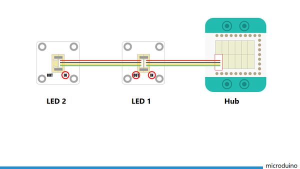
| + | *Setup 1:程序代码控制用的是A0,所以将灯用连接线将LED灯安装到Hub模块的A0接口上。用户可以自己改。 | ||
| + | [[File:CoreUSB_Ble_steup1.jpg|600px|center]] | ||
| + | LED灯的连接方法如上图,请注意连接顺序,从LED的IN接口接入,从OUT接口接出本应用最多可控制6个LED灯。 | ||
| + | [[File:CoreUSB_Ble_steup11.jpg|600px|center]] | ||
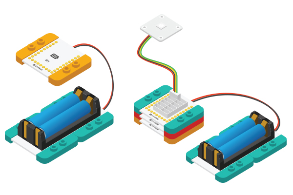
| + | *Setup 2:将激活后的电池盒与BM模块相连. | ||
| + | [[File:CoreUSB_Ble_steup2.jpg|600px|center]] | ||
| + | *Setup 3:将所有模块堆叠在一起,顺序随意,电路部分搭建完成。 | ||
| + | [[File:CoreUSB_Ble_steup2.jpg|600px|center]] | ||
| + | |||
| + | ==APP调试== | ||
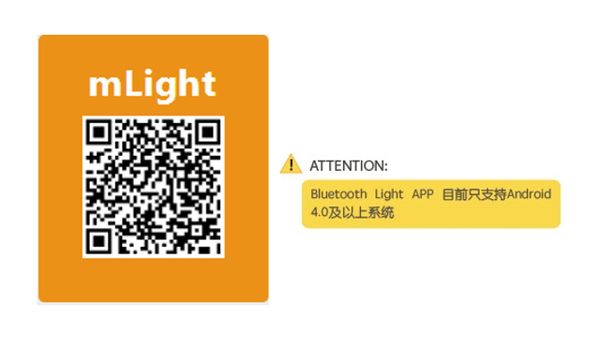
| + | *Setup 1:扫描左侧的二维码,下载Bluetooth Light APP。 | ||
| + | [[File:app_Ble_steup1.jpg|600px|center]] | ||
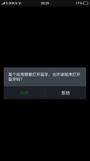
| + | *Setup 2:载安装App后,打开应用,如果没有打开蓝牙,系统会提示,选择打开。 | ||
| + | [[File:app_Ble_steup2.jpg|600px|center]] | ||
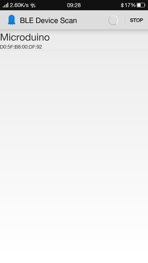
| + | *Setup 3:点击Scan,手机会开始搜索蓝牙设备,并显示在下方,选择名称为Microduino的设备. | ||
| + | [[File:app_Ble_steup3.jpg|600px|center]] | ||
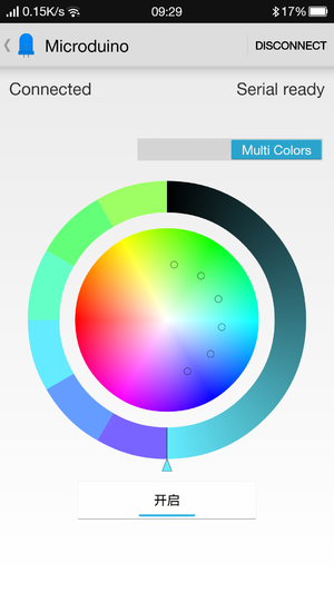
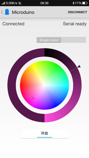
| + | *Setup 4:连接成功后,你就可以用手机来控制灯光了 | ||
| + | [[File:app_Ble_steup4.jpg|600px|center]] | ||
==软件调试== | ==软件调试== | ||
2015年9月2日 (三) 11:57的版本
| Language | English |
|---|
概述通过专用的Android App控制灯光的颜色和亮度。当手机不连接蓝牙能够自动变幻颜色,手机接入后,就可以通过手机控制灯的任意颜色了。 原理系统判断手机蓝牙和mCookie-BT是否建立了连接。当连接时,系统接收手机App传给mCookie-BT的数据,并解析出来,从而控制彩灯的颜色。当蓝牙断开连接时,系统则进入设定好的彩灯变幻模式,除非有蓝牙连接,否则循环在设定的模式中。
设备
文件:Ble lamp.jpg 600px 文档Android客户端: 注意:新版BT是蓝牙4.0,需要Android 4.3以上的系统才能支持。这里只提供Android的APP。 APP下载:'文件:Microduino-LAMP-APP.zip 准备
文件:CoreUSB Ble pc.jpg 600px
文件:103 BLE Light.jpg 600px 程序说明
#define my_Serial Serial1
my_Serial.begin(9600);
#define PIXEL_PIN    A0    // Digital IO pin connected to the NeoPixels.
#define PIXEL_COUNT  6

Adafruit_NeoPixel strip = Adafruit_NeoPixel(PIXEL_COUNT, PIXEL_PIN, NEO_GRB + NEO_KHZ800);
Adafruit_NeoPixel strip = Adafruit_NeoPixel(6, A0, NEO_GRB + NEO_KHZ800);
sscanf((char *)strstr((char *)buffer, "C:"), "C:%d,%d,%d,%d", &sta[0], &sta[1], &sta[2], &sta[3]);
从代码中可分析传输的协议为:“C:%d,%d,%d,%d”,并且将解析到的4个数据“%d”分别赋值给:sta[0], sta[1], sta[2], sta[3]。前三个数据分别为R,G,B的颜色值,最后一个则为控制模式选择。
    if (-1 == sta[3]) {
      colorSet(strip.Color(sta[0], sta[1], sta[2]));
    }
    else if ((0 <= sta[3]) && (sta[3] < PIXEL_COUNT)) {
      colorSet(strip.Color(sta[0], sta[1], sta[2]), sta[3]);
    }
如果sta[3]的值为-1,所有连接的灯都是同一个颜色,为接收到的“sta[0], sta[1], sta[2]”组合而来的颜色,即手机上选的颜色。否则将可以单独控制6个灯的颜色。
  if (c == '\n')
    {
      color_en = true;
      safe_ms = millis();
    }
  if (millis() - safe_ms > 3000)//用户可以改时间,3000单位是ms,即3S
  {
    safe_ms = millis();
    color_en = false;
  }
硬件搭建
LED灯的连接方法如上图,请注意连接顺序,从LED的IN接口接入,从OUT接口接出本应用最多可控制6个LED灯。
APP调试
软件调试
蓝牙模块串口使用,需要根据板子上的串口跳线确定,默认的通讯串口0:Serial #define my_Serial Serial
void ble()
{
  while (my_Serial.available())
  {
    char c = my_Serial.read();
    delay(2);

    if (c == 'C')
      buffer_sta = true;
    if (c == '\n')
    {
      color_en = true;
      safe_ms = millis();
    }
    if (buffer_sta)
    {
      buffer[buffer_num] = c;
      buffer_num++;
    }
    //  Serial.println(c);
    //Serial.println(color_en);
  }

  if (buffer_sta)
  {
    buffer_sta = false;

    sscanf((char *)strstr((char *)buffer, "C:"), "C:%d,%d,%d,%d", &sta[0], &sta[1], &sta[2], &sta[3]);

    for (int a = 0; a < buffer_num; a++)
      buffer[a] = NULL;
    buffer_num = 0;

    for (int i = 0; i < 4; i++)
    {
      Serial.print(sta[i]);
      Serial.print(",");
    }
    Serial.println(" ");

    if (-1 == sta[3]) {
      colorSet(strip.Color(sta[0], sta[1], sta[2]));
    }
    else if ((0 <= sta[3]) && (sta[3] < PIXEL_COUNT)) {
      colorSet(strip.Color(sta[0], sta[1], sta[2]), sta[3]);
    }
  }

  if (millis() - safe_ms > 3000)
  {
    safe_ms = millis();
    color_en = false;
  }
}
当有蓝牙连接时,蓝牙控制灯的颜色 if (-1 == sta[3]) {
colorSet(strip.Color(sta[0], sta[1], sta[2]));
}
else if ((0 <= sta[3]) && (sta[3] < PIXEL_COUNT)) {
colorSet(strip.Color(sta[0], sta[1], sta[2]), sta[3]);
}
否则自动控制颜色 if (!color_en)
{
rainbowCycle(10, 255, 0, 0, 0);
rainbowCycle(10, 255, 0, 0, 1);
rainbowCycle(10, 0, 255, 0, 0);
rainbowCycle(10, 0, 255, 0, 1);
rainbowCycle(10, 0, 0, 255, 0);
rainbowCycle(10, 0, 0, 255, 1);
rainbowCycle(10, 255, 0, 225, 0);
rainbowCycle(10, 255, 0, 225, 1);
rainbowCycle(10, 247, 139, 5, 0);
rainbowCycle(10, 247, 139, 5, 1);
rainbowCycle(10, 255, 255, 0, 0);
rainbowCycle(10, 255, 255, 0, 1);
rainbowCycle(10, 0, 255, 255, 0);
rainbowCycle(10, 0, 255, 255, 1);
for (int i = 0; i < 3; i++)
rainbow(30);
}
结果通过Microduino可以成功实现用手机控制彩灯,得到你想要的任意颜色。你也可以通过乐高搭建一个漂亮的外观。 视频 |
