“Microduino W5500网络(一)/zh”的版本间的差异
(→原理图) |
(→程序) |
||
| 第44行: | 第44行: | ||
==程序== | ==程序== | ||
| + | [[https://github.com/Microduino/Microduino_Tutorials/tree/master/Microduino_Advanced_Tutorial/W5500Code/MicroduinoW5500One MicroduinoW5500One]] | ||
==调试== | ==调试== | ||
2015年2月2日 (一) 03:04的最新版本
目的本教程将教大家如何ping通你的Microduino W5500。 设备
原理图
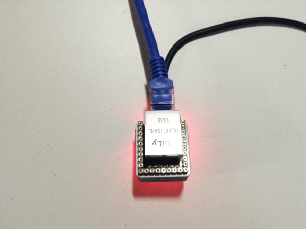
层层堆叠,再插上网线。 如下图所示: Microduino W5500引脚图:
程序调试步骤一:首先需要确保你的IDE中有_02_Microduino_Ethernet_WIZ库,如果没有下载放到你的IDE的libraries文件夹中,重启IDE。 步骤二:如果你的IDE的libraries文件夹中还有之前的Ethernet库的话,需要删除掉,因为之前的Ethernet是根据W5100协议编写的。 然后需要改动一下_02_Microduino_Ethernet_WIZ文件以使库函数与Microduino-W5500模块的引脚对应: 先找到_02_Microduino_Ethernet_WIZ库中的utility文件夹里的w5100.h 把代码中的 #define wiz_cs_pin 8 //CS_PIN 改为 #define wiz_cs_pin 10 //CS_PIN 就可以了。 步骤三:解释一下代码: 首先定义所要开启服务的IP地址和端口: // Enter a MAC address and IP address for your controller below.
// The IP address will be dependent on your local network.
// gateway and subnet are optional:
byte mac[] = {0xDE, 0xAD, 0xBE, 0xEF, 0xFE, 0xED};
IPAddress ip(192,168,1, 177);
IPAddress gateway(192,168,1, 1);
IPAddress subnet(255, 255, 255, 0);
// telnet defaults to port 23
EthernetServer server(23);
boolean alreadyConnected = false; // whether or not the client was connected previously
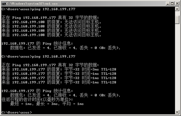
在代码中,我们开启一个23端口的服务并指定IP地址。 // initialize the ethernet device Ethernet.begin(mac, ip, gateway); 开启服务。 步骤四:下载代码并编译通过。 步骤五:ping! 检查一个设备是否正确联网,最简单的方法是ping它。在一个联网的计算机上输入ping 你要查看设备的IP地址 结果出现类似上图所示画面就说明连上网了。 视频 |

