“Microduino-Joypad Self-balance Robot Kit”的版本间的差异
(Created page with "{{Language|Microduino-Joypad Self-balance Robot Kit}} {| style="width: 800px;" |- | ==Outline== *Project:Microduino Self-balance Robot *Purpose:To control the self-bal...") |
(→Software Debugging) |
||
| 第170行: | 第170行: | ||
**The left switch is OutPutEnable and only when you turn it upside can you control the robot. The left joystick controls back and forth rotation, and the right joystick controls left and right-direction rotation. | **The left switch is OutPutEnable and only when you turn it upside can you control the robot. The left joystick controls back and forth rotation, and the right joystick controls left and right-direction rotation. | ||
[[File:Microduino_Joypad_ok3.jpg||600px|center|thumb]] | [[File:Microduino_Joypad_ok3.jpg||600px|center|thumb]] | ||
| + | |||
| + | *Select control mode | ||
| + | |||
| + | **We can select to control Quad. or Robot by【key3】. Meantime, under Robot mode, we can control the self-balance robot as well as BOXZ mini robot. “Black” means being selected. | ||
| + | [[File:Microduino_Joypad_config2.jpg||600px|center|thumb]] | ||
| + | |||
| + | **We can select somatosensory control mode by【key4】. Under the mode, you must stack [[Microduino-10DOF]] and select “MPU ON”. However, if under the joystick mode, you need to choose “MPU OFF”. | ||
| + | [[File:Microduino_Joypad_config3.jpg||600px|center|thumb]] | ||
| + | |||
| + | *Joystick adjustment 摇杆校准 | ||
| + | ** Rotate two joysticks to the fullest and press key 3 and enter Robot control mode after seeing no data change on TFT screen. | ||
| + | [[File:Microduino_Joypad_ config4.jpg||600px|center|thumb]] | ||
| + | |||
| + | *Turn on the switch on the left top and then you can have a control of the robot by moving the joystick and watching the data change on the screen. | ||
| + | [[File:Microduino_Joypad_ config5.jpg||600px|center|thumb]] | ||
| + | *The right switch is for range adjustment. Turn it to the top and you can fully control the self-balance robot. | ||
| + | [[File:Microduino_Joypad_ config6.jpg||600px|center|thumb]] | ||
==Attention== | ==Attention== | ||
2014年12月4日 (四) 02:23的最新版本
| Language | English |
|---|
目录Outline
Introduction
By using gyroscope and accelerometer (Microduino-10DOF) to detect altitude change of the robot, and ([[Microduino-Stepper) to drive the motor precisely and keep the balance of the system.
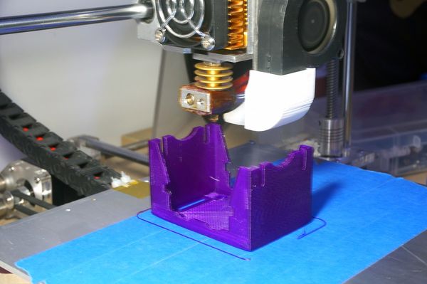
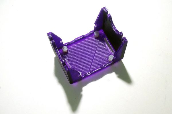
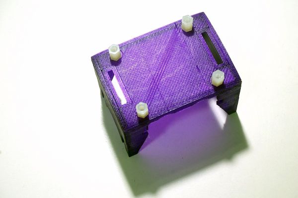
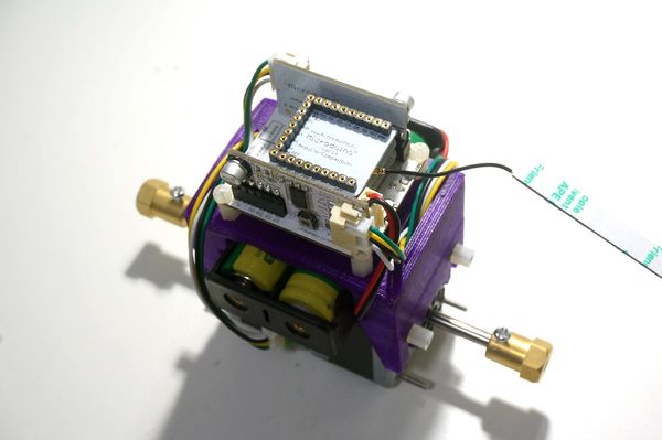
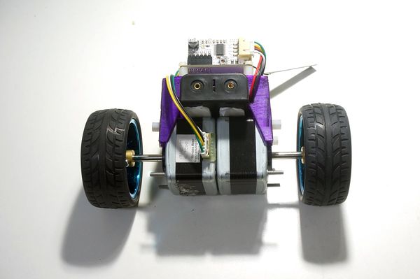
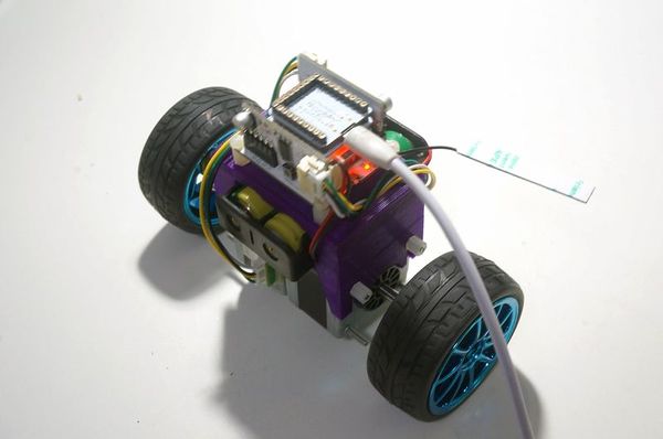
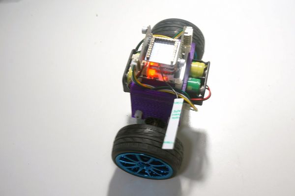
The robot is simply structured with a self-designed 3D-printer frame and a stepper as well as a self-balance system to adjust.
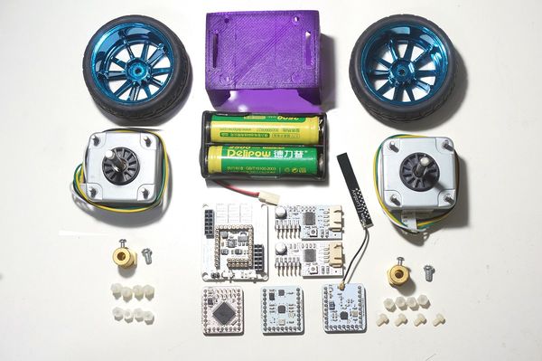
It is highly integrated with less wires and powerful modules, which adopts Nrf24 for wireless communication currently. Users can change communication option according to personal preference. Frame Buildup and DebuggingEquipment
Robot Buildup
Then, the whole structure buildup is finished. Software Debugging
You will need_03_Microduino_nRF_RF24 and _03_Microduino_nRF_RF24Network and please replace the original Arduino IDE libraries.
Remote Controller (Microduino-Joypad) BuildupHere we adopt Microduino-Joypad as the remote controller. Off course, you also other modules to build it. Equipment Requirement
Hardware Buildup
Software Debugging
You will need libraries below: _01_Microduino_GFX, _01_Microduino_TFT_ST7735 and _08_Microduino_Shield_Joypad;Please replace the original Arduino IDE libraries.
Attention
*Please first adjust the remote controller or it may lead to false control.
|
