“Rgb灯”的版本间的差异
(→设备) |
|||
| 第8行: | 第8行: | ||
==设备== | ==设备== | ||
| − | *'''[[Microduino-Core]]''' | + | *'''[[Microduino-Core/zh]]''' |
| − | *'''[[Microduino- | + | *'''[[Microduino-USBTTL/zh]]''' |
*其他硬件设备 | *其他硬件设备 | ||
| 第17行: | 第17行: | ||
**面包板 一个 | **面包板 一个 | ||
**跳线 一盒 | **跳线 一盒 | ||
| − | |||
| − | |||
==原理图== | ==原理图== | ||
2014年10月29日 (三) 07:06的版本
| Language | English |
|---|
目的本教程将教大家如何用Processing来控制一个RGB LED灯,通过一个颜色选择器来控制灯的颜色。 设备
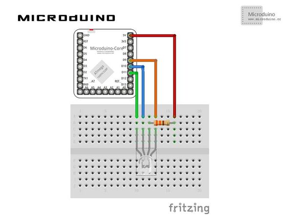
原理图
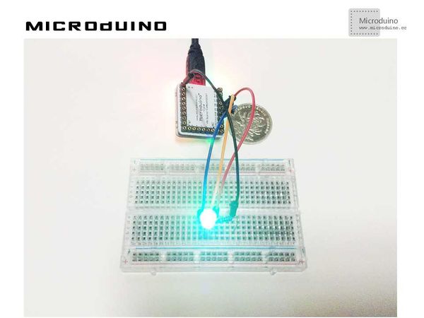
程序https://github.com/Microduino/Microduino_Tutorials/tree/master/Microduino_Processing/RGBLED 调试步骤一:按着原理图搭建硬件环境,像这样:
//显示调色板函数 void drawShadeWheel() {
for (int j = 0; j < steps; j++) {
color[] cols = {
color(255-(255/steps)*j, 255-(255/steps)*j, 0),
color(255-(255/steps)*j, (255/1.5)-((255/1.5)/steps)*j, 0),
color(255-(255/steps)*j, (255/2)-((255/2)/steps)*j, 0),
color(255-(255/steps)*j, (255/2.5)-((255/2.5)/steps)*j, 0),
color(255-(255/steps)*j, 0, 0),
color(255-(255/steps)*j, 0, (255/2)-((255/2)/steps)*j),
color(255-(255/steps)*j, 0, 255-(255/steps)*j),
color((255/2)-((255/2)/steps)*j, 0, 255-(255/steps)*j),
color(0, 0, 255-(255/steps)*j),
color(0, 255-(255/steps)*j, (255/2.5)-((255/2.5)/steps)*j),
color(0, 255-(255/steps)*j, 0),
color((255/2)-((255/2)/steps)*j, 255-(255/steps)*j, 0)
};
for (int i = 0; i < segs; i++) {
fill(cols[i]);
arc(width/2, height/2, radius, radius,
interval*i+rotAdjust, interval*(i+1)+rotAdjust);
}
radius -= segWidth;
}
}
 boolean mouseOverRect() { // Test if mouse is over square
   return ((mouseX >= 10) && (mouseX <= 190) && (mouseY >= 10) && (mouseY <=190));
 }
//得到颜色RGB值后,模拟写入pin9,10,11 void draw() {
// nothing happens here
if (mouseOverRect() == true)
{
color targetColor = get(mouseX, mouseY);
// get the component values:
int r = int(red(targetColor));
int g = int(green(targetColor));
int b = int(blue(targetColor));
// analogWirte to pin
arduino.analogWrite(9, r);
arduino.analogWrite(10, g);
arduino.analogWrite(11, b);
}
}
步骤三:下载代码并编译通过。
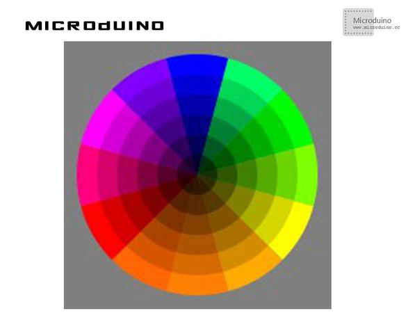
结果屏幕上会显示一个颜色选取器,像这样:
视频 |


