“Microduino-GPS”的版本间的差异
(→Test Microduino NEO-6M using FT232 and core module) |
(→Connection method) |
||
| 第150行: | 第150行: | ||
There are two connection methods: | There are two connection methods: | ||
1. Use the default pin (RX0、TX1): | 1. Use the default pin (RX0、TX1): | ||
| − | *You need the Microduino FT232R module to connect the PC, but can't superimpose the FT232R, NEO-6M and Core module directly. Because the FT232 and NEO-6M has the same RX/TX defination and position on board, but the normal serial communication should be cross | + | *You need the Microduino FT232R module to connect the PC, but can't superimpose the FT232R, NEO-6M and Core module directly. Because the FT232 and NEO-6M has the same RX/TX defination and position on board, but the normal serial communication should be cross connected with RX/TX. |
| − | ** | + | **Stack up the FT232 and microduino core, then conect them to PC with microUSB to download program; |
| − | ** | + | **Use jumpers to cross connect the RX0/TX1 of FT232 and NEO-6M, that is to connect the RX0 of NEO-6M to the TX1 of FT232, and the TX1 of NEO-6M to RX0 of FT232. |
| − | **Connect the 3V3 pin of NEO-6M module to 3V3 pin of FT232 | + | **Connect the 3V3 pin of NEO-6M module to 3V3 pin of FT232 and GND to GND for modules' power supply. |
[[File:Neo-6m debugging.jpg|thumb|400px|center|crossover configuration]] | [[File:Neo-6m debugging.jpg|thumb|400px|center|crossover configuration]] | ||
2. Use the changed jumper mode | 2. Use the changed jumper mode | ||
| − | If you have changed the jumper as | + | If you have changed the jumper as it describes above, you can stack up FT232, NEO-6M and Core module together, then connect to PC for debugging. |
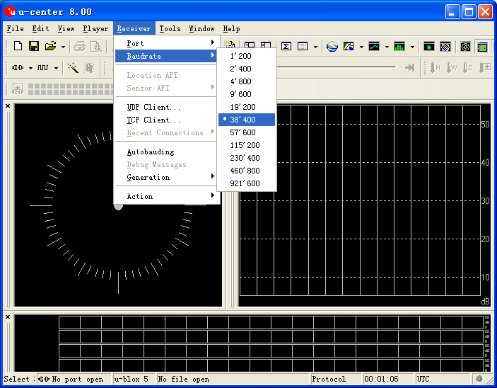
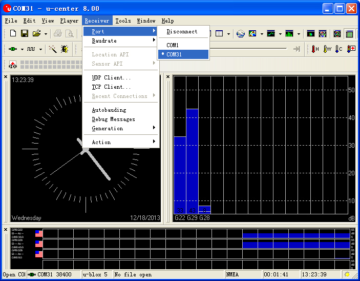
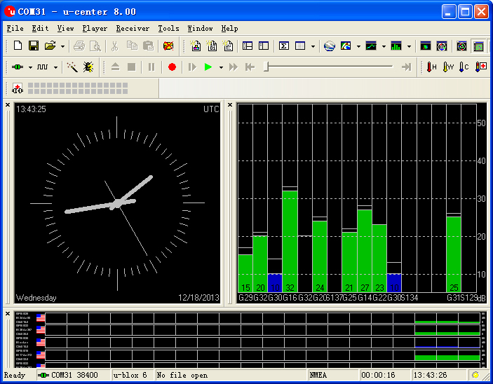
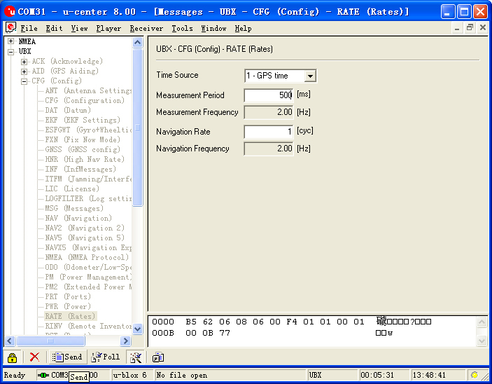
====Use u-center configuration module to update rage==== | ====Use u-center configuration module to update rage==== | ||
2014年7月28日 (一) 09:11的版本
| Language | English |
|---|
|
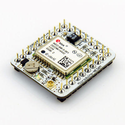
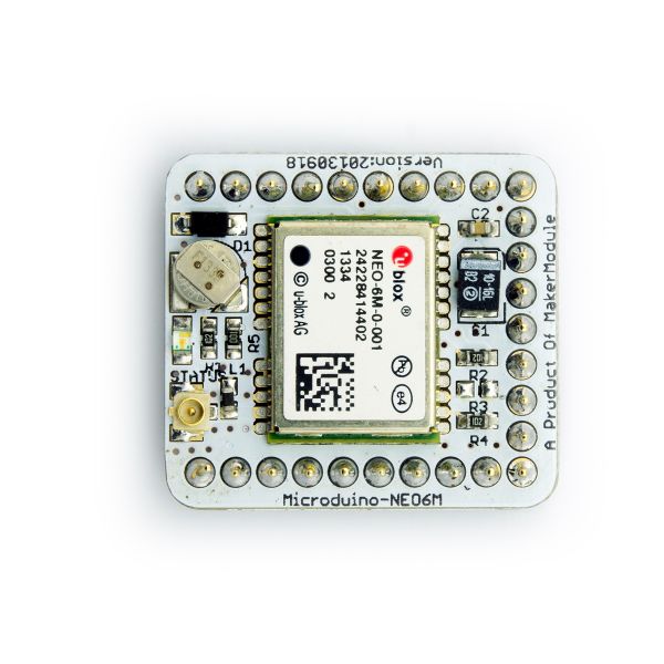
Microduino-GPS module maybe the most beautiful GPS module that you've seen. Its core module use UBLOX NEO-6M, high sensitivity, update rate up to 5Hz, using mini ceramic antenna with IPEX interface, and build-in a rechargeable battery backup. 目录Feature
| |||||||||||||||||||||||||||||
Specifications
Pin Description
文件:NEO6M-Pinout-2.jpg Microduino-NEO6M-Pinout 文件:NEO6M-Pinout-1.jpg Microduino-NEO6M-Pinout DocumentEagle PCB 文件:Microduino-NEO6M.zip
Main components
Development
Use PC to debug
Use FT232R and Core to download and debug
Arduino library and support package
How to use the library
PPS Status indicator
ApplicationDownload programTest Program:文件:Program Test NEO-6M.zip Test Microduino NEO-6M
Test Mocroduino NEO-6M using PCConnection methodThere are two connection methods: 1. Use the default pin (RX0、TX1):
文件:Neo-6m debugging.jpg crossover configuration 2. Use the changed jumper mode If you have changed the jumper as it describes above, you can stack up FT232, NEO-6M and Core module together, then connect to PC for debugging. Use u-center configuration module to update rage
BugHistoryPicture
Video |
