“Microduino-GPS”的版本间的差异
(→Download program) |
(→Test Microduino NEO-6M using FT232 and core module) |
||
| 第131行: | 第131行: | ||
Test Program:'''[[File:Program Test NEO-6M.zip]]''' | Test Program:'''[[File:Program Test NEO-6M.zip]]''' | ||
| − | ===Test Microduino NEO-6M | + | ===Test Microduino NEO-6M=== |
| − | * | + | *Hardware:Microduino FT232R,Microduino Core,Microduino OLED and Microduino NEO-6M; |
| − | * | + | *Software:Arduino IDE(version 1.0 and higher), Adafruit_GPS library and Microduino test program(Arduino part); |
| − | *Test environment:Open | + | *Test environment:Open area; |
| − | *Put the downloaded library | + | *Put the downloaded library into libraries of the Arduino IDE installation folder; |
| − | *Start Arduino IED,open the test | + | *Start Arduino IED,open the test program,choose "Microduino Core (Atmega328P@16M,5V)" and download directly; |
| − | * | + | *If using the default jumper pin (RX0,TX1): |
| − | **Unplug the Microduino NEO-6M module when downloading | + | **Unplug the Microduino NEO-6M module when downloading program;Since Microduino NEO-6M module has the same RX0/TX1 pin position with Microduino FT232R, the communication will be influenced if you stack these two modules together. |
| − | *After | + | *After the download, you'd better cut off the power supply firstly and then stack them for fear of causing short circuit. . |
| − | * | + | *Observe the OLED after the download is completed: |
| − | ** | + | **Data and time will be displayed half minute later; |
| − | ** | + | **Keep waiting. When you see the PPS indicator flashes, the index of the speed, latitude and longitude should be displayed. If not, please restart Microduino-Core. |
| − | * | + | *Players can change jumpers on the back of the module:Cut off the connection between the middle of the bonding pads and RX0/TX1, then weld the middle of the bonding pads to D2 and D3. The purpose of changing jumper is to download program easily. Once you change the jumper, you superimpose three boards together to download program. |
| − | **If you use the | + | **If you use the changed jumper connection method, it will change the serial connection from TX-RX0,RX-TX1 to TX-D2,RX-D3 between Microduino NEO-6M and Core. |
===Test Mocroduino NEO-6M using PC=== | ===Test Mocroduino NEO-6M using PC=== | ||
2014年7月28日 (一) 09:00的版本
| Language | English |
|---|
|
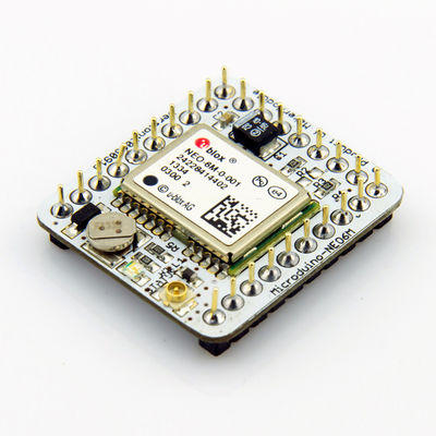
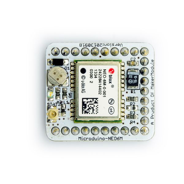
Microduino-GPS module maybe the most beautiful GPS module that you've seen. Its core module use UBLOX NEO-6M, high sensitivity, update rate up to 5Hz, using mini ceramic antenna with IPEX interface, and build-in a rechargeable battery backup. 目录Feature
| |||||||||||||||||||||||||||||
Specifications
Pin Description
文件:NEO6M-Pinout-2.jpg Microduino-NEO6M-Pinout 文件:NEO6M-Pinout-1.jpg Microduino-NEO6M-Pinout DocumentEagle PCB 文件:Microduino-NEO6M.zip
Main components
Development
Use PC to debug
Use FT232R and Core to download and debug
Arduino library and support package
How to use the library
PPS Status indicator
ApplicationDownload programTest Program:文件:Program Test NEO-6M.zip Test Microduino NEO-6M
Test Mocroduino NEO-6M using PCConnection methodThere are two connection methods: 1. Use the default pin (RX0、TX1):
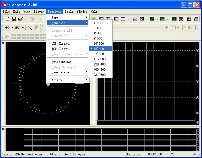
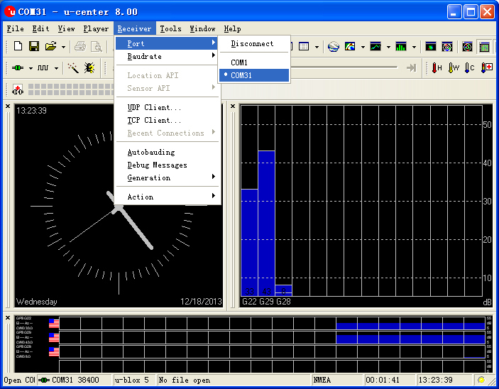
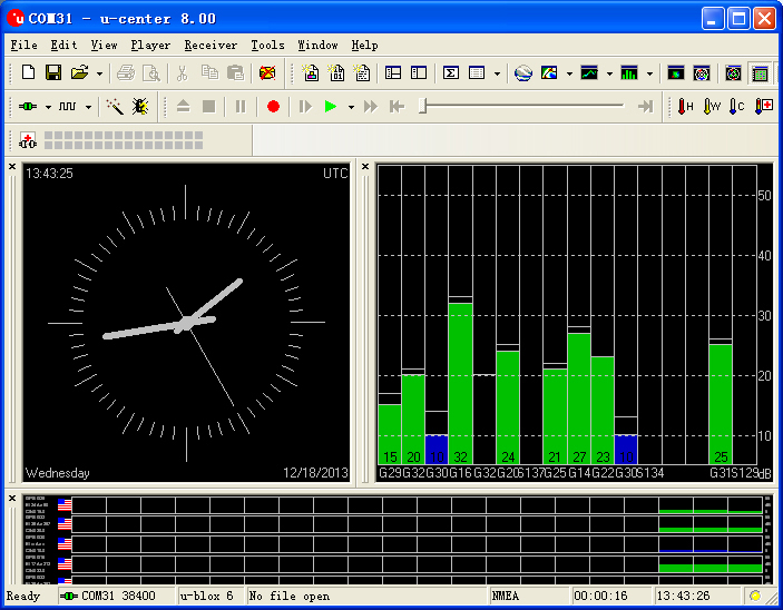
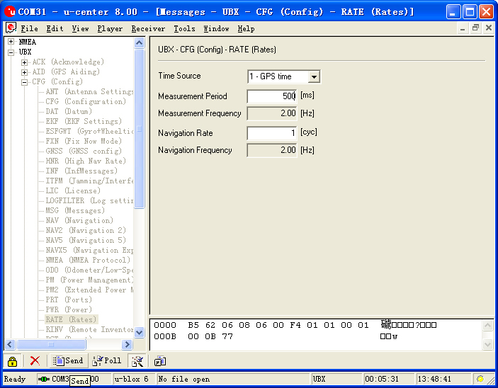
文件:Neo-6m debugging.jpg crossover configuration 2. Use the changed jumper mode If you have changed the jumper as upper described, you can supperipose FT232, NEO-6M and Core module together, then connect to PC to debug directly. Use u-center configuration module to update rage
BugHistoryPicture
Video |
