“Lesson 43--Microduino Rotary encoder”的版本间的差异
(Created page with "{{Language | 第四十三课--Microduino 旋转编码器使用}} {| style="width: 800px;" |- | ==Objective== This experiment will through Microduino to decode the rotary encod...") |
(没有差异)
|
2014年3月31日 (一) 14:25的最新版本
| Language | English |
|---|
目录ObjectiveThis experiment will through Microduino to decode the rotary encoder, judge the movement direction and whether it was pressed. Equipment
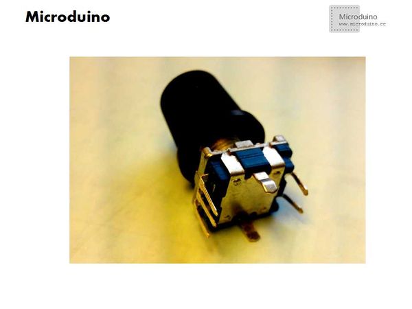
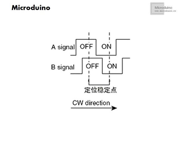
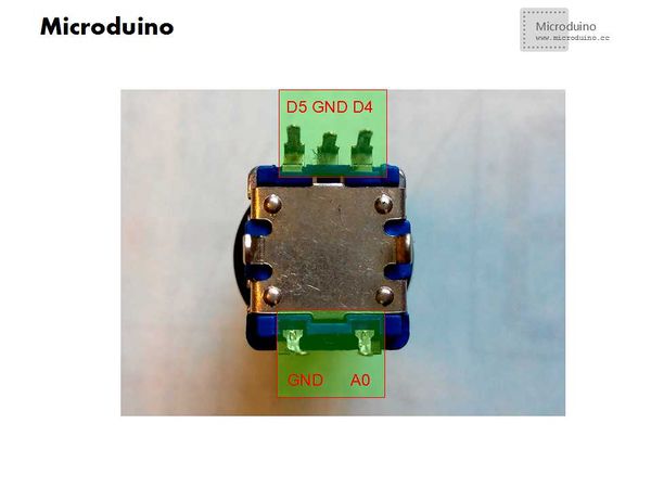
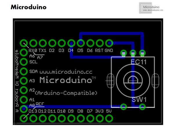
Rotary encoderRotary encoderThis kind of rotary encoder has turn left, turn right and press three functions. The function of the press just like we use the button. Rotate the encoder, it caan produce the pulse signal that has a different phase, which can be used to distinguish the opposite direction. If the output 1 as the high electricity level, and a high level in output 2 too, then switch rotated as clockwise, otherwise output 2 is a low level, it must be counterclockwise. Pin DiagramSchematicProgramDownload test program: https://github.com/Microduino/Microduino_Tutorials/tree/master/Microduino_Advanced/Microduino_rotary_encoder Debug
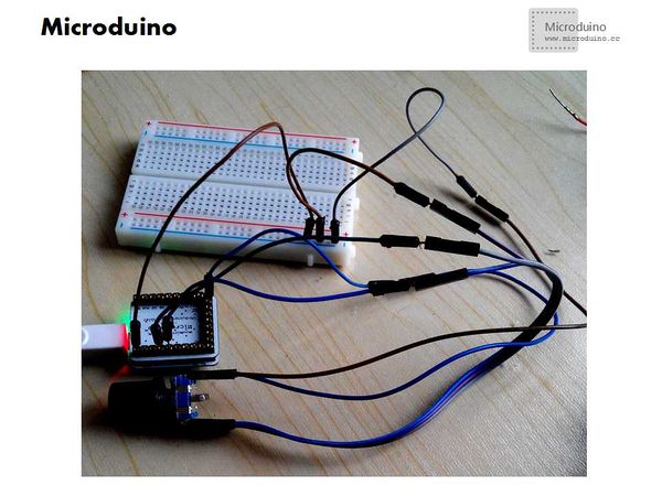
Set up the circuit follow the schematic
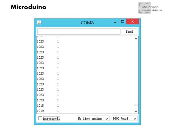
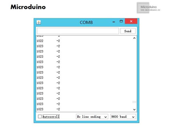
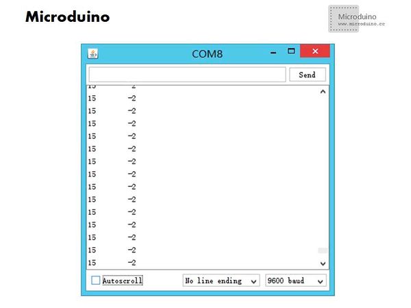
ResultAccording to the serial port monitor returned data to judge the state of rotary encoder. The playsers can make other application based on this experiment. Video |
