“Microduino点阵模块显示BMP彩图/zh”的版本间的差异
| 第42行: | 第42行: | ||
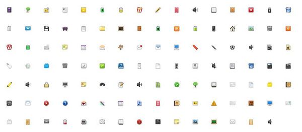
**首先,我们先找个小的图片素材 | **首先,我们先找个小的图片素材 | ||
**可以在这个网站找图片素材:[http://www.pp3.cn/icon/size/16_16/2011/1128/821.html] | **可以在这个网站找图片素材:[http://www.pp3.cn/icon/size/16_16/2011/1128/821.html] | ||
| − | [[File:BMP1.jpg||600px| | + | [[File:BMP1.jpg||600px|center]] |
| − | |||
| − | |||
*'''Step.2:''' | *'''Step.2:''' | ||
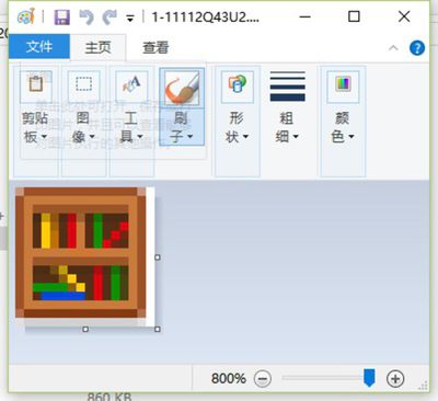
**随便选一个存起来 | **随便选一个存起来 | ||
**用画图工具打开 | **用画图工具打开 | ||
**另存为24位的BMP格式 | **另存为24位的BMP格式 | ||
| − | [[File:BMP2.jpg||400px|left]] | + | [[File:BMP2.jpg||400px|left]] [[File:BMP3.jpg||400px|top]] |
| − | [[File:BMP3.jpg||400px| | + | |
| − | |||
| − | |||
*'''Step.3:''' | *'''Step.3:''' | ||
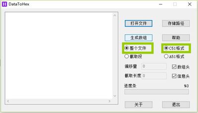
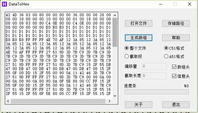
**下载并且打开工具:[https://www.microduino.cn/wiki/index.php/File:DataToHex.zip DataToHex] | **下载并且打开工具:[https://www.microduino.cn/wiki/index.php/File:DataToHex.zip DataToHex] | ||
| 第61行: | 第57行: | ||
[[File:BMP4.jpg||400px|left]] | [[File:BMP4.jpg||400px|left]] | ||
| − | [[File:BMP5.jpg||400px| | + | [[File:BMP5.jpg||400px|top]] |
| + | |||
| − | |||
| − | |||
*'''Step.4:''' | *'''Step.4:''' | ||
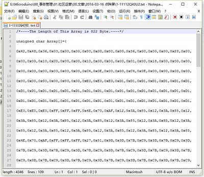
**接下来在这个BMP目录内打开生成好的同名TXT文件 | **接下来在这个BMP目录内打开生成好的同名TXT文件 | ||
| 第70行: | 第65行: | ||
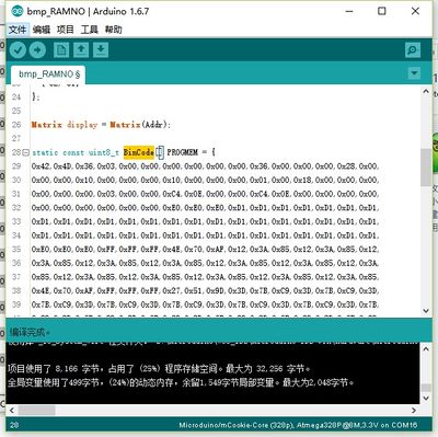
**替换示例程序中的BinCode数组中内容 | **替换示例程序中的BinCode数组中内容 | ||
**下载你的程序到点阵中(2x2阵列) | **下载你的程序到点阵中(2x2阵列) | ||
| − | [[File:BMP6.jpg||400px|left]] | + | [[File:BMP6.jpg||400px|left]][[File:BMP7.jpg||400px|top]] |
| − | [[File:BMP7.jpg||400px| | ||
==程序烧写== | ==程序烧写== | ||
2016年3月25日 (五) 11:53的版本
| Language | English |
|---|
概述
材料清单
实验原理
因为我们的点阵屏也是24位的,理所当然我就按24位BMP图片加上了位图显示功能(函数:drawBMP(x,y,data)) 这个函数是基于Adafruit的spitftbitmap例程移植的,将BMP图像储存在Flash储存中,不多占用内存空间 程序下载
操作说明

程序烧写
代码说明#include "Microduino_Matrix.h"
uint8_t Addr[MatrixPix_X][MatrixPix_Y] = {
{ 64, 63},
{ 62, 61}
};
Matrix display = Matrix(Addr);
static const uint8_t BinCode[] PROGMEM = {
};
void setup(void) {
delay(6000);
Serial.begin(115200);
Wire.begin();
display.clearDisplay();
display.drawBMP(0, 0, BinCode);
}
void loop() {
}
FAQ |
