“Main Page”的版本间的差异
(→下载程序) |
|||
| 第1行: | 第1行: | ||
| − | {{Language| | + | {{Language|Main Page}} |
| − | {| style=" | + | {| class="titlebox" width="800px" style="border:2px solid #000000; -moz-border-radius:5px 5px 5px 5px; -webkit-border-radius:5px 5px 5px 5px;" cellspacing=0 cellpadding=0 |
| + | ! style="background:#000000; border-radius:2px; padding:5px; color:#ffffff;" | <div style="font-size:180%;text-align:center;">Welcome to the Microduino Wiki</div> | ||
|- | |- | ||
| | | | ||
| − | + | {| | |
| − | |||
| − | |||
| − | |||
| − | |||
| − | |||
| − | |||
| − | |||
| − | |||
| − | |||
| − | |||
| − | {| | ||
|- | |- | ||
| − | | | + | |[[file:wiki.jpg|800px|left]] |
| + | |} | ||
|- | |- | ||
| − | | | + | | |
| + | {| | ||
|- | |- | ||
| − | | | + | | Small size, great power! Microduino and mCookie bring powerful, small, stackable electronic hardware to makers, designers, engineers, students and curious tinkerers of all ages. Build open-source projects or create innovative new ones. |
| − | + | <br> | |
| − | + | All Microduino and mCookie boards are Arduino-compatible. Experienced makers can write their own programs in the Arduino IDE and upload their code to the hardware via USB, while novices can take advantage of open-source Scratch programming to drag and drop pre-written code. | |
| − | |||
| − | |||
| − | |||
| − | |||
| − | |||
| − | |||
| − | |||
| − | |||
| − | |||
| − | |||
| − | |||
| − | |||
| − | + | <br> | |
| + | Microduino dramatically decreases the size and cost of design prototyping, improves flexibility of Arduino-compatible boards, and enhances the user experience for any age or skill level. | ||
| + | <br> | ||
| − | |||
| − | + | Microduino and mCookie modules, sensors and accessories are perfect for idea realization, prototype development, low-volume production and old-fashioned fun. | |
| − | |||
| − | |||
| − | |||
| − | |||
| − | |||
| − | + | |} | |
| − | + | |} | |
| − | |||
| − | + | <br> | |
| − | |||
| − | |||
| − | + | =Microduino Upin27 Series= | |
| − | [[ | + | {| style="width: 800px;"| colspan="2" | |
| + | |- | ||
| + | | style="width:400px" align="left"| | ||
| + | =='''[[Microduino Series]]'''== | ||
| + | <br> | ||
| + | [[file:Microduino-CoreList-rect.jpg|200px|left]] | ||
| − | === | + | | style="width:400px" align="left"| |
| − | + | =='''[[Microduino Tutorials and Projects]]'''== | |
| − | + | <br> | |
| − | + | [[file:Microduino-Projects.png|400px|left]] | |
| − | + | |- | |
| − | [[ | + | |} |
| + | <br><br> | ||
| − | == | + | =mCookie UPin27 Series= |
| + | {| style="width: 800px;" | colspan="2" | | ||
| + | |- | ||
| + | | style="width:400px" align="left"| | ||
| + | =='''[[mCookie Series]]'''== | ||
| + | <br> | ||
| + | [[file:mCookie-rect.jpg|200px|left]] | ||
| − | + | | style="width:400px" align="left"| | |
| + | == '''[[mCookie Tutorials and Projects]]'''== | ||
| + | <br> | ||
| + | [[file:mCookie-Projects.jpg|400px|left]] | ||
| + | |- | ||
| + | |} | ||
| + | <br><br> | ||
| − | + | {| style="width: 800px;" | colspan="2" | | |
| − | + | =MicroWrt HPin44 Series= | |
| + | |- | ||
| + | | style="width:400px" align="left"| | ||
| + | =='''[[MicroWrt Series]]'''== | ||
| + | <br> | ||
| + | [[file:MicroWRT-rect.jpg|200px|left]] | ||
| − | + | | style="width:400px" align="left"| | |
| + | =='''[[MicroWrt Tutorials and Projects]]'''== | ||
| + | <br> | ||
| + | [[file:MicroWrt-Extension-rect.jpg|200px|left]] | ||
| + | |- | ||
| + | | | ||
| + | |} | ||
| + | <br> | ||
| + | <br> | ||
| − | + | {| style="width: 800px;" | colspan="2" | | |
| − | + | =MicroPi HPin88 Series= | |
| + | |- | ||
| + | | style="width:400px" align="left"| | ||
| + | =='''[[MicroPi Series]]'''== | ||
| + | <br> | ||
| + | [[file:MicroCookie-Zen-rect.jpg|200px|left]] | ||
| − | + | | style="width:400px" align="left"| | |
| + | =='''[[MicroPi Tutorials and Projects]]'''== | ||
| + | <br> | ||
| + | [[file:MicroCookie-Nux-rect.jpg|200px|left]] | ||
| + | |- | ||
| + | |} | ||
| + | <br><br> | ||
| − | + | {| style="width: 800px;" | colspan="2" | | |
| − | |||
| − | |||
| − | + | =Microduino Sensor Series= | |
| + | |- | ||
| + | | style="width:400px" align="left"| | ||
| + | =='''[[Microduino Sensor Series]]'''== | ||
| + | <br> | ||
| + | [[file:Microduino-sensors.jpg|200px|left]] | ||
| − | + | | style="width:400px" align="left"| | |
| − | + | =='''[[Microduino Sensor Tutorials and Projects]]'''== | |
| − | + | <br> | |
| + | [[file:Microduino-sensors.jpg|200px|left]] | ||
| + | |} | ||
| + | <br><br> | ||
| − | |||
| − | |||
| − | |||
| − | + | =Additional Information= | |
| − | + | Fritzing: '''[[File:Microduino-Fritzing.zip]]'''<br> | |
| − | + | Microduino Community Projects: https://www.microduino.cc/project <br> | |
| − | + | Microduino IDE Github Repository: [[https://github.com/wasdpkj/Microduino-IDE Microduino-IDE]]<br> | |
| − | + | Microduino Getting Started: '''[[AVR Core: Getting Started]]''' <br/> | |
| − | + | mCookie Frequently Asked Questions: [[mCookie Frequently Asked Questions|FAQ]] | |
| − | |||
| − | |||
| − | |||
| − | |||
| − | |||
| − | |||
| − | |||
| − | |||
| − | |||
| − | |||
| − | + | <br> | |
| − | + | <br> | |
| − | |||
| − | |||
| − | |||
| − | |||
| − | |||
| − | |||
| − | |||
| − | |||
| − | |||
| − | |||
| − | |||
| − | |||
| − | |||
| − | |||
| − | |||
| − | |||
| − | |||
| − | |||
| − | |||
| − | |||
| − | |||
| − | |||
| − | |||
| − | |||
| − | |||
| − | |||
| − | |||
| − | |||
| − | |||
| − | |||
| − | |||
| − | |||
| − | |||
| − | |||
| − | |||
| − | |||
| − | |||
| − | |||
| − | |||
| − | |||
| + | {| class="wikitable" style="width:800px;border:2px solid #000000; -moz-border-radius:5px 5px 5px 5px; -webkit-border-radius:5px 5px 5px 5px;" cellspacing=0 cellpadding=0 | ||
| + | | | ||
| + | This Wiki was built on '''June 11, 2013'''. There are '''[[Special:SpecialPages|{{NUMBEROFARTICLES}} pages]]''', '''[[Special:NewFiles|{{NUMBEROFFILES}} files uploaded]]''' and '''[[Special:Statistics|{{NUMBEROFEDITS}} revisions]]'''. <br>To learn more information, please visit '''[[Special:RecentChanges|Recent Changes]]'''. | ||
| + | <br> | ||
| + | <br>Technical Support: support@microduino.cc | ||
| + | <br>Business Inquiries: sales@microduino.cc | ||
|} | |} | ||
2016年3月11日 (五) 03:43的最新版本
| Language | English |
|---|
| Welcome to the Microduino Wiki
| |
|---|---|
|
| |
|
目录
Microduino Upin27 Series
Microduino Series
|
Microduino Tutorials and Projects
|
mCookie UPin27 Series
mCookie Series
|
mCookie Tutorials and Projects
|
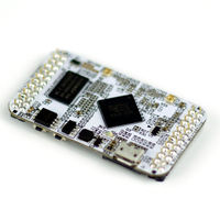
MicroWrt Series
|
MicroWrt Tutorials and Projects
|
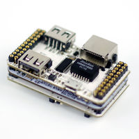
MicroPi Series
|
MicroPi Tutorials and Projects
|
Microduino Sensor Series
|
Microduino Sensor Tutorials and Projects
|
Additional Information
Fritzing: 文件:Microduino-Fritzing.zip
Microduino Community Projects: https://www.microduino.cc/project
Microduino IDE Github Repository: [Microduino-IDE]
Microduino Getting Started: AVR Core: Getting Started
mCookie Frequently Asked Questions: FAQ
|
This Wiki was built on June 11, 2013. There are 1,708 pages, 26,539 files uploaded and 43,325 revisions. |

