“Lesson 1--Microduino "LED and a Breadboard"”的版本间的差异
小 (Changliu818@yahoo.com moved page Lesson 1--LED flashes experiments (using bread board) to Lesson 1--Microduino "LED and a Breadboard") |
|||
| 第4行: | 第4行: | ||
| | | | ||
==Objective== | ==Objective== | ||
| − | + | This lesson will teach you how to use Microduino to control a LED. Once you are familiar with Microduino's I/O ports, you will have developed solid fundamentals for future projects. | |
==Equipment== | ==Equipment== | ||
*'''[[Microduino-Core]]''' | *'''[[Microduino-Core]]''' | ||
| − | Microduino-Core is | + | Microduino-Core is an 8-bit microcontroller development board based on Atmel ATmega328P, ATmega168PA series. It is open source and compatible with the Arduino UNO. |
| − | |||
| − | |||
*'''[[Microduino-FT232R]]''' | *'''[[Microduino-FT232R]]''' | ||
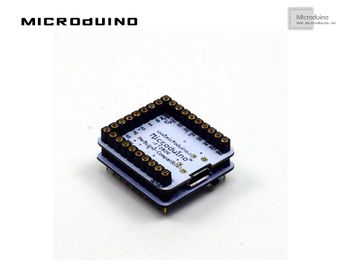
| − | + | This module is used to upload your program into the core. You can stack it directly onto the Microduino-Core or Microduino-Core+ and communicate with your PC. Similar to many smartphones, it uses a MicroUSB as the download port. | |
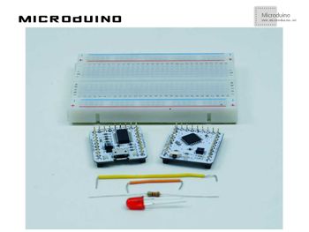
| − | + | *Other hardware equipment: | |
| + | **1x Box of breadboard jumper wires | ||
| + | **1x Breadboard | ||
| + | **8x LEDs (Light-Emitting Diodes) | ||
| + | **1x 220ohm resistor | ||
| + | **1x USB Data cable | ||
| − | + | [[File:lesson1Main.jpg|350px|center|thumb]] | |
| − | + | [[File:lesson1All.jpg|350px|center|thumb]] | |
| − | |||
| − | |||
| − | |||
| − | |||
| − | |||
| − | [[File:lesson1Main.jpg| | ||
| − | [[File:lesson1All.jpg| | ||
===Breadboard=== | ===Breadboard=== | ||
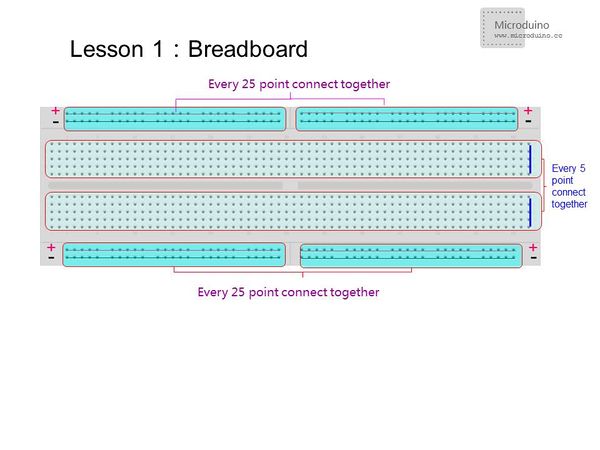
| − | + | For the two long strips in the middle,every 5 points are connected vertically. For the four strips running along the outer board, every 25 points are connected horizontally. For the outer two strips, one row is used for GND and the other is for VCC. | |
| + | <br><br> | ||
| + | Note: In some breadboards, all 50 points are connected together in the outer strips. Be aware of the connection format when working on projects. | ||
[[File:breadboard.jpg|600px|center|thumb]] | [[File:breadboard.jpg|600px|center|thumb]] | ||
===Resistor and LED=== | ===Resistor and LED=== | ||
| − | + | Resistors prevent your LED from being damaged by limiting the voltage supplied. Max voltage for red and green LEDs is 1.8 ~ 2.4V, blue and white is 2.8 ~ 4.2V. 3mmLED rated current is 1 ~ 10mA, 5mmLED rated current is 5 ~ 25mA, and 10mmLED rated current is 25 ~ 100mA. Use Resistance = Voltage / Current to calculate the resistance. 200-400 ohms of resistance is usually adequate. | |
| − | How to Judge the | + | '''How to Judge the Positive/Negative Ends of a LED Light''' |
| − | + | Method One: Take a look inside the LED light. The pin with a bigger bracket is negative and the one with a smaller bracket is positive. | |
| − | + | Method Two: For a new LED light, you can tell from the length of the pins. The longer pin is positive and and the shorter pin is negative. | |
| − | Test a LED Light via a Multimeter | + | '''Test a LED Light via a Multimeter''' |
| − | When using the analog multimeter to test a diode, you must choose the "Rxl0k" | + | When using the analog multimeter to test a diode, you must choose the "Rxl0k" slot since the voltage of the battery inside the multimeter is only 1.5V when the multimeter is under the "R×lk" slot, lower than the voltage drop of a 3V LED light. In that case, it is impossible to test LED lights no matter what connection method you adopt. While the analog multimeter is under the "R×l0k" slot, you can test the LED light for the voltage of the battery is about 9V(or 15V), higher than the voltage drop. |
Since the black probe of the analog multimeter shows positive and the red probe shows negative, you need to connect the black probe to the positive of the LED light and the red probe to the negative. If the LED light goes on, then it works. | Since the black probe of the analog multimeter shows positive and the red probe shows negative, you need to connect the black probe to the positive of the LED light and the red probe to the negative. If the LED light goes on, then it works. | ||
| − | Different from the analog multimeter, the digital multimeter shows contrary electrode. Adopting right connection method, you can prove the LED | + | Different from the analog multimeter, the digital multimeter shows contrary electrode. Adopting right connection method, you can prove the LED is working when it lights up. |
| + | |||
| + | ==Experimental Schematic== | ||
| + | There are two connection methods: | ||
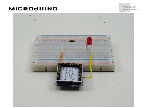
| − | + | *Method One: Connect the positive end (anode) to GND and the negative end (cathode) to Microduino digital I/O port 13. This creates a high level connection. | |
| − | + | *Method Two: Connect the anode to Microduino digital I/O port 13 and the cathode to VCC. This creates a low level connection. | |
[[File:schematic.jpg|600px|center|thumb]] | [[File:schematic.jpg|600px|center|thumb]] | ||
| 第64行: | 第65行: | ||
} | } | ||
void loop() { | void loop() { | ||
| − | digitalWrite(led, HIGH); //I/O port 13 output High. | + | digitalWrite(led, HIGH); //Set I/O port 13 output as High.In high level connection: LED will turn on; low level connection: LED will turn off |
delay(1000); // delay 1s | delay(1000); // delay 1s | ||
| − | digitalWrite(led, LOW); //I/O port 13 output Low. | + | digitalWrite(led, LOW); //Set I/O port 13 output as Low.In high level connection: LED will turn off; low level connection: LED will turn on |
delay(1000); // delay 1s | delay(1000); // delay 1s | ||
} | } | ||
</source> | </source> | ||
| − | *Using function millis() | + | *Using function millis():Returns the number of milliseconds from when the program started running. |
| + | |||
<source lang="cpp"> | <source lang="cpp"> | ||
int ledPin=13; | int ledPin=13; | ||
| 第96行: | 第98行: | ||
</source> | </source> | ||
| − | + | It is better to use millis() than the delay() function since it uses less resources and causes fewer delays on the system. | |
| − | ==Download | + | ==How To Download The Program== |
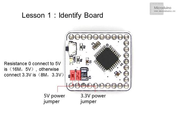
| − | *Choose the board type in "tools" | + | *Choose the board type in "tools". The "Microduino-Core(ATmega328P@16M,5V)" is used in this experiment. There are two types of 328 boards, so you need identify which type of board you are using. You can check the 0 resistor's connection method to identify. |
[[File:boardtype.jpg|600px|center|thumb]] | [[File:boardtype.jpg|600px|center|thumb]] | ||
| − | *Choose COM port. | + | *Choose COM port in "tools". The serial port is different for everyone's computer. It is usually ports 3-5. The COM port is in "properties"->"device manager" in your computer. You also can double-click "Advanced" to change the COM port by port settings. |
| − | *Compile | + | |
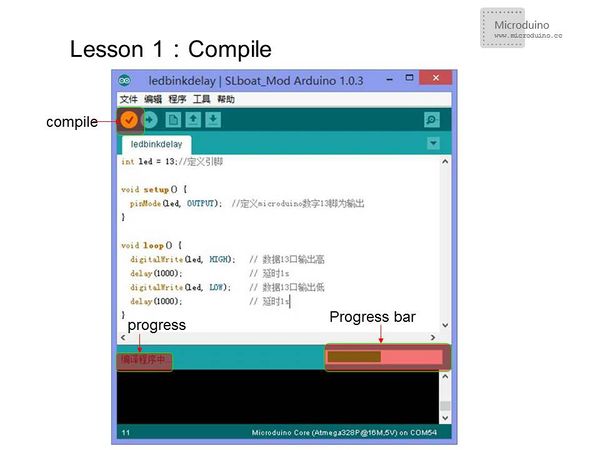
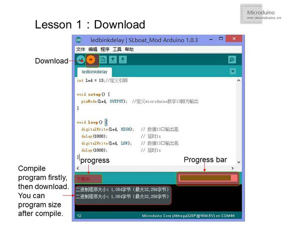
| + | *Compile and then download program | ||
[[File:compile.jpg|600px|center|thumb]] | [[File:compile.jpg|600px|center|thumb]] | ||
| 第109行: | 第112行: | ||
==Result== | ==Result== | ||
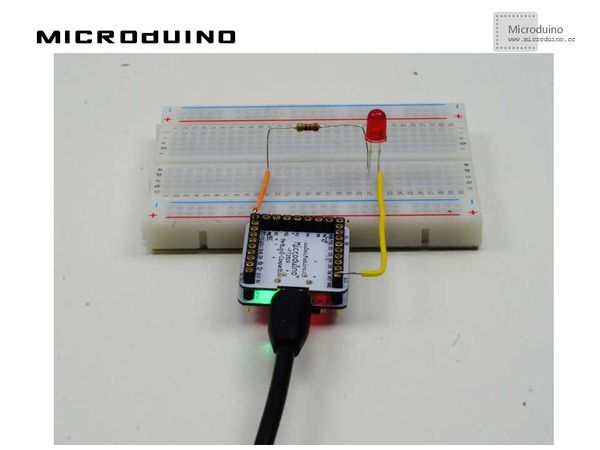
| − | After the download, you can see LED | + | After the download, you can see the LED flash once every second. |
[[File:lesson1OK.jpg|600px|center|thumb]] | [[File:lesson1OK.jpg|600px|center|thumb]] | ||
==Video== | ==Video== | ||
| − | + | http://v.youku.com/v_show/id_XNzEwMDA0NzA4.html | |
|} | |} | ||
2015年7月12日 (日) 09:21的版本
| Language | English |
|---|
目录[隐藏]ObjectiveThis lesson will teach you how to use Microduino to control a LED. Once you are familiar with Microduino's I/O ports, you will have developed solid fundamentals for future projects. EquipmentMicroduino-Core is an 8-bit microcontroller development board based on Atmel ATmega328P, ATmega168PA series. It is open source and compatible with the Arduino UNO. This module is used to upload your program into the core. You can stack it directly onto the Microduino-Core or Microduino-Core+ and communicate with your PC. Similar to many smartphones, it uses a MicroUSB as the download port.
BreadboardFor the two long strips in the middle,every 5 points are connected vertically. For the four strips running along the outer board, every 25 points are connected horizontally. For the outer two strips, one row is used for GND and the other is for VCC.
Resistor and LEDResistors prevent your LED from being damaged by limiting the voltage supplied. Max voltage for red and green LEDs is 1.8 ~ 2.4V, blue and white is 2.8 ~ 4.2V. 3mmLED rated current is 1 ~ 10mA, 5mmLED rated current is 5 ~ 25mA, and 10mmLED rated current is 25 ~ 100mA. Use Resistance = Voltage / Current to calculate the resistance. 200-400 ohms of resistance is usually adequate. How to Judge the Positive/Negative Ends of a LED Light Method One: Take a look inside the LED light. The pin with a bigger bracket is negative and the one with a smaller bracket is positive. Method Two: For a new LED light, you can tell from the length of the pins. The longer pin is positive and and the shorter pin is negative. Test a LED Light via a Multimeter When using the analog multimeter to test a diode, you must choose the "Rxl0k" slot since the voltage of the battery inside the multimeter is only 1.5V when the multimeter is under the "R×lk" slot, lower than the voltage drop of a 3V LED light. In that case, it is impossible to test LED lights no matter what connection method you adopt. While the analog multimeter is under the "R×l0k" slot, you can test the LED light for the voltage of the battery is about 9V(or 15V), higher than the voltage drop. Since the black probe of the analog multimeter shows positive and the red probe shows negative, you need to connect the black probe to the positive of the LED light and the red probe to the negative. If the LED light goes on, then it works. Different from the analog multimeter, the digital multimeter shows contrary electrode. Adopting right connection method, you can prove the LED is working when it lights up. Experimental SchematicThere are two connection methods:
Program
int led = 13;// Define the PIN
void setup() {
  pinMode(led, OUTPUT);  // Define the I/O port 13 as output
}
void loop() {
digitalWrite(led, HIGH); //Set I/O port 13 output as High.In high level connection: LED will turn on; low level connection: LED will turn off
delay(1000);               // delay 1s
digitalWrite(led, LOW); //Set I/O port 13 output as Low.In high level connection: LED will turn off; low level connection: LED will turn on
delay(1000);               // delay 1s
}
int ledPin=13;
#define TIME 1000
long time1=0,time2=0;
void setup()
{
  pinMode(ledPin,OUTPUT);
}
void loop()
{
if(millis()<time2+TIME)
{
digitalWrite(ledPin,HIGH);
time1=millis();
}
else
{
digitalWrite(ledPin,LOW);
if(millis()>time1+TIME)
time2=millis();
}
}
It is better to use millis() than the delay() function since it uses less resources and causes fewer delays on the system. How To Download The Program
ResultAfter the download, you can see the LED flash once every second. Video |
