“数码管控制”的版本间的差异
(→程序) |
(→调试) |
||
| 第54行: | 第54行: | ||
//在setup()中初始化绘制数码管的8个led | //在setup()中初始化绘制数码管的8个led | ||
for (int i = 0; i < leds.length; i ++ ) { // Initialize each led and output pin using a for loop. | for (int i = 0; i < leds.length; i ++ ) { // Initialize each led and output pin using a for loop. | ||
| − | |||
arduino.pinMode(microduinoPins[i], Arduino.OUTPUT); | arduino.pinMode(microduinoPins[i], Arduino.OUTPUT); | ||
} | } | ||
| + | |||
| + | leds[0] = new LED(50, 350, 50,200,1); | ||
| + | leds[1] = new LED(100, 550, 200,50,2); | ||
| + | leds[2] = new LED(300, 350, 50,200,3); | ||
| + | leds[3] = new LED(350, 550, 50,50,4); | ||
| + | leds[4] = new LED(300, 100, 50,200,5); | ||
| + | leds[5] = new LED(100, 50, 200,50,6); | ||
| + | leds[6] = new LED(50, 100, 50,200,7); | ||
| + | leds[7] = new LED(100, 300, 200,50,8); | ||
//在draw()中绘制数码管并判断led的亮灭并把状态发送到Microduino | //在draw()中绘制数码管并判断led的亮灭并把状态发送到Microduino | ||
| 第63行: | 第71行: | ||
//draw segemnt lables | //draw segemnt lables | ||
| − | text (segmentLables[i], | + | text (segmentLables[i], leds[i].xpos, leds[i].ypos); |
if (leds[i].button) {//switch led on/off | if (leds[i].button) {//switch led on/off | ||
2014年6月11日 (三) 08:29的版本
目的本教程将教大家如何用processing来控制一个共阴极数码管。 设备
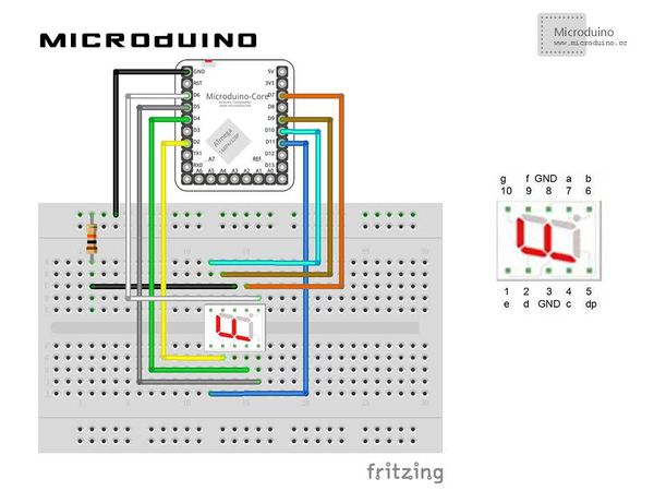
原理图程序调试步骤一:按着原理图搭建硬件环境,像这样:
本例需要两端的代码,Processing端和Microduino端 Microduino: 使用firmata的StandardFirmata程序。 Processing: //定义8个LED用来表示一个数码管。 LED[] leds = new LED[8]; // An array of 8 led objects! //定义对应数码管引脚1,2,.......10的Microduino引脚。 int microduinoPins[] = {//Correspondence microduino pin for 7 segment
11,2,4,5,6,7,9,10};
//定义数码管LED标签 String segmentLables[]={"1-e","2-d","3-c","4-dp","5-b","6-a","7-f","8-g"};
 for (int i = 0; i < leds.length; i ++ ) { // Initialize each led and output pin using a for loop.
   arduino.pinMode(microduinoPins[i], Arduino.OUTPUT);
 }

 leds[0] = new LED(50, 350, 50,200,1);
 leds[1] = new LED(100, 550, 200,50,2);
 leds[2] = new LED(300, 350, 50,200,3);
 leds[3] = new LED(350, 550, 50,50,4);
 leds[4] = new LED(300, 100, 50,200,5);
 leds[5] = new LED(100, 50, 200,50,6);
 leds[6] = new LED(50, 100, 50,200,7);
 leds[7] = new LED(100, 300, 200,50,8);
//在draw()中绘制数码管并判断led的亮灭并把状态发送到Microduino for (int i = 0; i < leds.length; i ++ ) { // Run each Car using a for loop.
leds[i].display();
//draw segemnt lables
text (segmentLables[i], leds[i].xpos, leds[i].ypos);
if (leds[i].button) {//switch led on/off
arduino.digitalWrite(microduinoPins[i], Arduino.HIGH);
}
else {
arduino.digitalWrite(microduinoPins[i], Arduino.LOW);
}
}
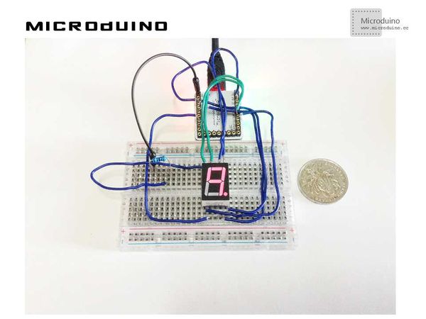
步骤三:下载代码并编译通过。 步骤四:运行后,在processing中会出现8个LED,鼠标点击每个led看数码管会有什么反应。 结果鼠标点击后对应的数码管LED会亮起或熄灭,像这样
视频 |

