“指南针”的版本间的差异
(→Objective) |
|||
| 第2行: | 第2行: | ||
|- | |- | ||
| | | | ||
| − | == | + | ==目的== |
| − | + | 本教程将教大家如何用Microduino-10DOF模块测到的磁场强度数据在Processing中显示一个指南针。 | |
| − | == | + | ==设备== |
*'''[[Microduino-Core]]''' | *'''[[Microduino-Core]]''' | ||
*'''[[Microduino-FT232R]]''' | *'''[[Microduino-FT232R]]''' | ||
*'''[[Microduino-10DOF]]''' | *'''[[Microduino-10DOF]]''' | ||
| − | * | + | *其他硬件设备 |
| − | ** | + | **USB数据连接线 一根 |
| − | == | + | ==原理图== |
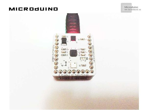
| − | + | 直接使用Microduino-10DOF上的HMC5883L磁场强度传感器 | |
| − | == | + | ==程序== |
| − | + | 见 compassMicroduino | |
compass_simulator | compass_simulator | ||
| − | == | + | ==调试== |
| − | + | 步骤一:按着原理图搭建硬件环境,像这样: | |
[[File:compass_simulatorConnectionDiagram.jpg|600px|center|thumb]] | [[File:compass_simulatorConnectionDiagram.jpg|600px|center|thumb]] | ||
| − | + | 步骤二:解释一下代码: | |
| − | + | 本例需要两端的代码,Processing端和Microduino端 | |
Microduino: | Microduino: | ||
| − | // | + | //得到磁场强度数据后输出到串口以便Processing显示 |
void loop() | void loop() | ||
| 第48行: | 第48行: | ||
Processing: | Processing: | ||
| − | // | + | //得到第一个串口的数据,并定义如果有换行就缓存 |
| + | // is always my Arduino, so I open Serial.list()[0]. | ||
// Open whatever port is the one you're using. | // Open whatever port is the one you're using. | ||
myPort = new Serial(this, Serial.list()[0], 9600); | myPort = new Serial(this, Serial.list()[0], 9600); | ||
myPort.bufferUntil('\n'); // Trigger a SerialEvent on new line | myPort.bufferUntil('\n'); // Trigger a SerialEvent on new line | ||
| − | // | + | //把从Microduino接收到的数据取出来后以不同颜色的曲线图的形式显示在屏幕上,并标上标尺 |
| − | + | 函数说明: | |
| − | // | + | //绘制磁场指针 |
arrow(int x1, int y1, int x2, int y2, color c) | arrow(int x1, int y1, int x2, int y2, color c) | ||
| − | // | + | //判断是否可转换为数字 |
isNumeric(String str) | isNumeric(String str) | ||
| − | + | 步骤三:下载代码并编译通过。 | |
| − | + | 步骤四:运行后,用一块磁铁改变一下磁场,看看指针是否变化。 | |
| − | == | + | ==结果== |
| − | + | 屏幕上会显示一个简单的指南针,指针会随着磁场走,像这样: | |
[[File:compass_simulatorResult.jpg|600px|center|thumb]] | [[File:compass_simulatorResult.jpg|600px|center|thumb]] | ||
| − | == | + | ==视频== |
|} | |} | ||
2014年5月21日 (三) 07:22的版本
目的本教程将教大家如何用Microduino-10DOF模块测到的磁场强度数据在Processing中显示一个指南针。 设备
原理图直接使用Microduino-10DOF上的HMC5883L磁场强度传感器 程序见 compassMicroduino compass_simulator 调试步骤一:按着原理图搭建硬件环境,像这样:
本例需要两端的代码,Processing端和Microduino端 Microduino: //得到磁场强度数据后输出到串口以便Processing显示 void loop()
{
mag.getHeading(&mx, &my, &mz);
Serial.print(mx);
Serial.print(",");
Serial.println(my);
}
Processing: //得到第一个串口的数据,并定义如果有换行就缓存 // is always my Arduino, so I open Serial.list()[0].
// Open whatever port is the one you're using.
myPort = new Serial(this, Serial.list()[0], 9600);
myPort.bufferUntil('\n'); // Trigger a SerialEvent on new line
//把从Microduino接收到的数据取出来后以不同颜色的曲线图的形式显示在屏幕上,并标上标尺 函数说明: //绘制磁场指针 arrow(int x1, int y1, int x2, int y2, color c) //判断是否可转换为数字 isNumeric(String str) 步骤三:下载代码并编译通过。 步骤四:运行后,用一块磁铁改变一下磁场,看看指针是否变化。 结果屏幕上会显示一个简单的指南针,指针会随着磁场走,像这样:
视频 |
