“第三课--按钮控制的LED开关/zh”的版本间的差异
(→结果) |
(→程序) |
||
| 第36行: | 第36行: | ||
<source lang="cpp"> | <source lang="cpp"> | ||
const int buttonPin = 2; // 定义按键输入引脚 | const int buttonPin = 2; // 定义按键输入引脚 | ||
| − | const int ledPin = | + | const int ledPin = 11; //定义led引脚 |
int buttonState = 0; //初始化按键值 | int buttonState = 0; //初始化按键值 | ||
void setup() { | void setup() { | ||
| 第55行: | 第55行: | ||
<source lang="cpp"> | <source lang="cpp"> | ||
const int buttonPin = 2; // 定义按键输入引脚 | const int buttonPin = 2; // 定义按键输入引脚 | ||
| − | const int ledPin = | + | const int ledPin = 11; |
int buttonState = 0; | int buttonState = 0; | ||
2014年6月4日 (三) 17:23的版本
| Language | English |
|---|
目的前两个实验介绍了如何用软件直接控制led灯的亮灭。如果我们增加一个按键,通过按键来控制led的亮灭,就可以实现硬件与软件的结合。前面实际上是Microduino的I/O口作为输出去控制led,增加按键如何去监测按键输入的信号呢?今天以按键为例讲讲Microduino如何作为输入使用。 设备
文件:Lesson3All.jpg 600px 按键
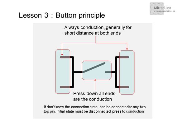
若用此封装按键制作PCB时,若不好布线,可利用它有两对引脚始终导通作为导线布线。
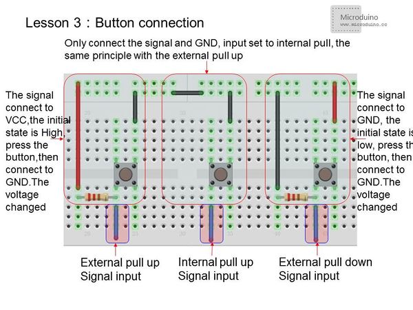
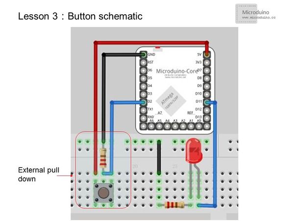
原理图采用外部下拉,没按下时为低“0”,按下为高。
文件:Lesson3Setup.jpg 600px 程序
const int buttonPin = 2;     // 定义按键输入引脚
const int ledPin =  11;     //定义led引脚
int buttonState = 0;        //初始化按键值
void setup() {
  pinMode(ledPin, OUTPUT);    //设置led引脚为输出状态
  pinMode(buttonPin, INPUT); //设置按键引脚为输入状态
}
void loop(){
  buttonState = digitalRead(buttonPin);//从指定的数字引脚读取数值,是高还是低。
  if (buttonState == HIGH) {
    digitalWrite(ledPin, HIGH); //如果按键信号是高,则led点亮(led接法阳极接控制脚,阴极接GND)
  }
  else {
    digitalWrite(ledPin, LOW); //否则熄灭
  }
}
const int buttonPin = 2;     // 定义按键输入引脚
const int ledPin =  11;

int buttonState = 0;
boolean led;         //定义led为布尔型(true或false)
void setup() {
  pinMode(ledPin, OUTPUT);
  // pinMode(buttonPin, INPUT); //设置按键引脚为输入状态
  pinMode(buttonPin, INPUT_PULLUP);//设置按键引脚为内部上拉输入状态
}
void loop(){
  buttonState = digitalRead(buttonPin);
  if (buttonState ==HIGH)
//外部下拉,因为这样起始状态为低,只有按下才是高,按下才翻转,否则不按时则会闪烁
  {
    delay(200);                     //短暂延时,防抖
    // delay(1000);               //长按
    // if (buttonState == LOW)  //判断是否还是低
    led=!led;                   //led状态翻转
  }
  digitalWrite(ledPin, led);
}
此实验需要注意按键的防抖,可以调整延时时间,或者在按键信号变化两端加104电容,电压信号不会突变,稳定点。 按键防抖详细参考:http://www.geek-workshop.com/thread-74-1-1.html digitalRead()用法读一个引脚的值,返回值为HIGH或低。 结果
文件:Lesson3Result.jpg 600px 视频 |


