“Sensor-Dot Matrix-S2/zh”的版本间的差异
| 第1行: | 第1行: | ||
| − | {{Language|Microduino-Dot Matrix}} | + | {{Language|Microduino-Dot Matrix-S2}} |
{| style="width: 800px;" | {| style="width: 800px;" | ||
|- | |- | ||
| | | | ||
| − | [[file:Dot | + | [[file:Dot Matrix-S2front.jpg|thumb|400px|right]] |
| − | Microduino-Dot | + | Microduino-Dot Matrix-S2的产品编号是:'''MSDL32''' |
| + | |||
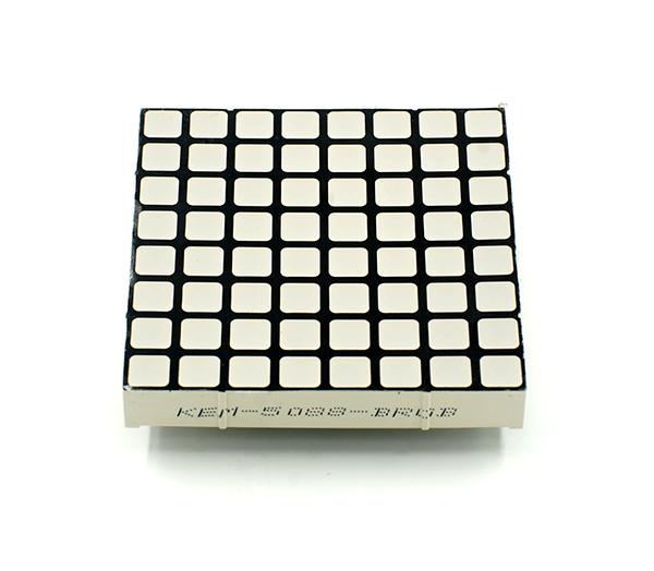
| + | Microduino-Dot Matrix-S2模块是一个8x8单色LED显示矩阵模块,可单个点阵或多个点阵级联(组合成不同的形状)使用,用于显示图片或文字,甚至是简单的动画效果。 | ||
| − | |||
==特色== | ==特色== | ||
| + | *8x8点阵,尺寸32mm*32mm | ||
| + | *每个点32级亮度调节 | ||
| + | *支持IIC通讯协议,IIC地址可设(1~64),点阵序列采用平面直角坐标系 | ||
| + | *板载2个IIC接口,便于多个点阵进行级联 | ||
| − | + | ==规格== | |
| − | * | + | *传感器电压 |
| − | * | + | **5V工作电压 |
| − | * | + | *传感器电流 |
| − | * | + | **不超过300mA |
| − | * | ||
| − | * | ||
| + | *传感器大小 | ||
| + | **板子大小:60mm*60mm | ||
| + | **1.27mm间距的4Pin接口与sensorhub相连 | ||
| − | + | *功能描述 | |
| − | * | + | **8x8点阵 |
| − | ** | + | *每个点32级亮度调节 |
| − | * | + | **支持IIC通讯协议,IIC地址可设(1~64),点阵序列采用平面直角坐标系 |
| − | ** | + | **板载2个IIC接口,便于多个点阵进行级联 |
| − | |||
| − | |||
| − | ** | ||
| − | |||
| − | |||
*接法 | *接法 | ||
| − | * | + | **本传感器可连接到核心的I2C接口 |
| + | **支持多传感器级联,最多支持64个点阵 | ||
==文档== | ==文档== | ||
| − | + | *原理图:[[File:Dot Matrix-S2 PCB]] | |
| + | *可用IDE以下库中的示例程序自行进行实验:[https://github.com/wasdpkj/Microduino-IDE-Support/tree/master/arduino-ide-Support/%5B1.6.x%5D-hardware(library)/hardware/Microduino/avr/libraries '''_01_Microduino_DotMatrix'''] | ||
==开发== | ==开发== | ||
===程序下载=== | ===程序下载=== | ||
| − | *下载并解压程序'''[[File:Dot Matrix- | + | *下载并解压程序'''[[File:Dot Matrix-S2.zip]]''' |
===程序烧写=== | ===程序烧写=== | ||
{{Upload | {{Upload | ||
| 第43行: | 第46行: | ||
|nameB=[[Microduino-USBTTL/zh]] | |nameB=[[Microduino-USBTTL/zh]] | ||
|boardName=Microduino/mCookie-Core(328p)、Atmega328P@16M,5V | |boardName=Microduino/mCookie-Core(328p)、Atmega328P@16M,5V | ||
| − | |fileName=Dot Matrix- | + | |fileName=Dot Matrix-S2.ino |
}} | }} | ||
===硬件搭建=== | ===硬件搭建=== | ||
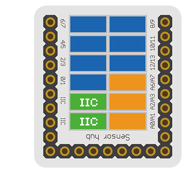
| − | *参考下图将Sensor-Dot Matrix- | + | *参考下图将Sensor-Dot Matrix-S2传感器连接'''[[Microduino-Sensorhub/zh]]'''的I2C接口。 |
<br> | <br> | ||
[[file:Microduino-sensorhub_I2C.JPG|thumb|400px|left]] | [[file:Microduino-sensorhub_I2C.JPG|thumb|400px|left]] | ||
| 第61行: | 第64行: | ||
==代码说明== | ==代码说明== | ||
| − | uint8_t Addr[MatrixPix_X][MatrixPix_Y] = { 64 } | + | *定义单个点阵的IIC地址 |
| − | + | uint8_t Addr[MatrixPix_X][MatrixPix_Y] = { //1x1 | |
| − | + | { 64} | |
| − | + | }; | |
| − | + | ||
| − | + | *定义2x2级联点阵的IIC地址 | |
| − | + | uint8_t Addr[MatrixPix_X][MatrixPix_Y] = { //2x2 | |
| − | + | { 64, 63}, | |
| − | + | { 62, 61} | |
| − | + | }; | |
| − | + | ||
| − | + | *定义1x4级联点阵的IIC地址 | |
| − | + | uint8_t Addr[MatrixPix_X][MatrixPix_Y] = { //1x4 | |
| − | + | { 64, 63, 62 , 61} | |
| − | + | }; | |
| − | + | ||
| − | + | *获取已接入设备的数目 | |
| − | + | int16_t getMatrixNum() | |
| − | + | ||
| − | + | *获取已接入设备的IIC地址 | |
| − | + | getDeviceAddr(_a) //num | |
| − | + | ||
| − | + | *获取X轴上点阵的数目 | |
| − | + | getWidth() | |
| − | + | ||
| − | + | *获取Y轴上点阵的数目 | |
| − | + | getHeight() | |
| − | + | ||
| − | + | *设置点阵坐标像素的亮灭 | |
| − | + | setLed(_row, _col, _state) //row, col, state | |
| − | |||
| − | |||
| − | + | *设置点阵坐标像素的亮度 | |
| + | setLedBrightness(_row, _col, _value) //row, col, value | ||
| + | |||
| + | *清空屏幕 | ||
| + | clearDisplay() | ||
| + | |||
| + | *设置点阵亮度 | ||
| + | setBrightness(_value) //value | ||
| + | |||
| + | *字符流动显示 | ||
| + | writeString(_c, _t, _col) //[char*], time, col | ||
| + | |||
| + | *十六进制位图显示 | ||
| + | drawBMP(_row, _col , _w, _h, logo) //row, col, width, height, file | ||
| + | |||
| + | *BMP位图显示(可参考[https://www.microduino.cn/wiki/index.php/Microduino%E7%82%B9%E9%98%B5%E6%A8%A1%E5%9D%97%E6%98%BE%E7%A4%BABMP%E5%BD%A9%E5%9B%BE/zh '''点阵模块显示BMP彩图''']) | ||
| + | drawBMP(_row, _col, logo) //row, col, file | ||
| + | |||
| + | *函数用来画实心矩形 | ||
| + | drawBox(_row, _col, _w, _h) //row, col, width, height | ||
| + | |||
| + | *函数用来画实心圆角矩形 | ||
| + | drawRBox(_row, _col, _w, _h, _r) //row, col, width, height, rad | ||
| + | |||
| + | *函数用来画空心矩形 | ||
| + | drawFrame(_row, _col, _w, _h) //row, col, width, height | ||
| + | |||
| + | *函数用来画空心圆角矩形 | ||
| + | drawRFrame(_row, _col, _w, _h, _r) //row, col, width, height, rad | ||
| + | |||
| + | *函数用来画空心圆 | ||
| + | drawCircle(_row, _col, _r) //row, col, rad | ||
| + | |||
| + | *函数用来画实心圆 | ||
| + | drawDisc(_row, _col, _r) //row, col, rad | ||
| − | + | *用来画直线 | |
| + | drawLine(_row, _col, _row1, _col1) //row start, col start, row end, col end | ||
| + | ==应用== | ||
| + | *'''[[开源LED点阵屏幕/zh]]''' | ||
| + | *'''[[开源LED点阵时钟/zh]]''' | ||
==图库== | ==图库== | ||
[[file:Microduino-DotMatrix-F.jpg|thumb|600px|center|Front]] | [[file:Microduino-DotMatrix-F.jpg|thumb|600px|center|Front]] | ||
[[file:Microduino-DotMatrix-B.jpg|thumb|600px|center|Back]] | [[file:Microduino-DotMatrix-B.jpg|thumb|600px|center|Back]] | ||
2016年9月13日 (二) 12:53的版本
| Language | English |
|---|
|
Microduino-Dot Matrix-S2的产品编号是:MSDL32 Microduino-Dot Matrix-S2模块是一个8x8单色LED显示矩阵模块,可单个点阵或多个点阵级联(组合成不同的形状)使用,用于显示图片或文字,甚至是简单的动画效果。 特色
规格
文档
开发程序下载
程序烧写
硬件搭建
点阵地址设置方法
代码说明
 uint8_t Addr[MatrixPix_X][MatrixPix_Y] = {  //1x1
   { 64}
 };
 uint8_t Addr[MatrixPix_X][MatrixPix_Y] = {  //2x2
   { 64, 63},
   { 62, 61}
 };
 uint8_t Addr[MatrixPix_X][MatrixPix_Y] = {  //1x4
   { 64, 63, 62 , 61}
 };
int16_t getMatrixNum()
getDeviceAddr(_a) //num
getWidth()
getHeight()
setLed(_row, _col, _state) //row, col, state
setLedBrightness(_row, _col, _value) //row, col, value
clearDisplay()
setBrightness(_value) //value
writeString(_c, _t, _col) //[char*], time, col
drawBMP(_row, _col , _w, _h, logo) //row, col, width, height, file
drawBMP(_row, _col, logo) //row, col, file
drawBox(_row, _col, _w, _h) //row, col, width, height
drawRBox(_row, _col, _w, _h, _r) //row, col, width, height, rad
drawFrame(_row, _col, _w, _h) //row, col, width, height
drawRFrame(_row, _col, _w, _h, _r) //row, col, width, height, rad
drawCircle(_row, _col, _r) //row, col, rad
drawDisc(_row, _col, _r) //row, col, rad
drawLine(_row, _col, _row1, _col1) //row start, col start, row end, col end 应用图库 |


