“Microduino-Cube-V1”的版本间的差异

来自Microduino Wikipedia
跳转至: 导航搜索
(Created page with "Microduino-Cube-V1 {| style="width: 800px;" |- | 400px|thumb|right|Microduino-Cube-V1 ==Features== *Pin compatible with Arduino uno; *Two UPin-...")
 
Pkj讨论 | 贡献
Specifications
第22行: 第22行:
 
**OLED fixed base;
 
**OLED fixed base;
 
**Two serial ports, RX0、TX0(Serial) and D2、D3(Serial1);
 
**Two serial ports, RX0、TX0(Serial) and D2、D3(Serial1);
**Tw IIC interfaces;
+
**Two IIC interfaces;
 
**Two analogy button interfaces, and connect to A7;
 
**Two analogy button interfaces, and connect to A7;
 
**Seven analogy buttons. Two buttons on base board and connected to A6. Five button on overlay board and connected to base analogy button interface by DuPont line;
 
**Seven analogy buttons. Two buttons on base board and connected to A6. Five button on overlay board and connected to base analogy button interface by DuPont line;
第38行: 第38行:
 
**Overlay board: use to fix the five analogy buttons, OLED;
 
**Overlay board: use to fix the five analogy buttons, OLED;
 
[[file:Microduino-Cube--Pinout1-Pinout4.jpg|800px|thumb|center|Microduino-Cube-S1]]
 
[[file:Microduino-Cube--Pinout1-Pinout4.jpg|800px|thumb|center|Microduino-Cube-S1]]
 +
 
==Document==
 
==Document==
 
Eagle PCB local download
 
Eagle PCB local download

2014年3月6日 (四) 03:39的版本

Microduino-Cube-V1

Microduino-Cube-V1

Features

  • Pin compatible with Arduino uno;
  • Two UPin-27 standard interfaced female heades, and the corresponding pin has connected;
  • Define unified interface Microduino specification and contain rich peripheral modules. Set up the quick connection with other Microduino modules and sensors easily and flexibly;
  • Two Female Heade's each pin interconnects and vertical arrangement on the board which can reduce the overlay height;
  • Onboard analog buttons, extended interface;

Specifications

  • Electrical specifications
    • MicroUSB power supply;
    • 3.3V regular;
    • Select the 5V or 3.3V power via PWR jumper, default is 3.3V;
    • Onboard power supply (5V、PWR) indicator;
  • Extended pin
    • Onboard reset button;
    • OLED fixed base;
    • Two serial ports, RX0、TX0(Serial) and D2、D3(Serial1);
    • Two IIC interfaces;
    • Two analogy button interfaces, and connect to A7;
    • Seven analogy buttons. Two buttons on base board and connected to A6. Five button on overlay board and connected to base analogy button interface by DuPont line;
    • Two group sensor interface, can be combined by jumper. The player can make the connection by yoursefl, as follows:
      • PWR,GND,A3 or PWR,GND,A6;
      • PWR,D5,GND or D4,D5,GND。
文件:Microduino-Cube-V1-Pinout1.jpg
Microduino-Cube-V1-Pinout
文件:Microduino-Cube-V1-Pinout2.jpg
Microduino-Cube-V1-Pinout
文件:Microduino-Cube-V1-Pinout3.jpg
Microduino-Cube-V1-Pinout


  • Components
    • base board:with two UPin-27 standard interface;
    • Overlay board: use to fix the five analogy buttons, OLED;

Document

Eagle PCB local download Main components:

Development

It can be used with other Microduino modules, sensor to achieve specific functions.

Application

  • You can download the test example, and combine OLED to test two analogy of Microduino-Cube-V1, test program Microduino-Cube-V1-Text.zip
  • Prepared hardware:Microduino FT232R, Microduino Core, Microduino-Cube-V1, Microduino OLED;
  • Prepared software:Microduino example program (Arduino part), Arduino IDE(1.0 release and upper);
  • Open the example program in IDE, select the board "Microduino Core (Atmega328P@16M,5V)", download directly;
  • After the download is completed, OLED displays similar patterns with analogy keyboard. Press each button on floor and roof analog buttons can simulate the corresponding position's button.

Buy

History

Picture

Front

Microduino-Cube-V1 Front

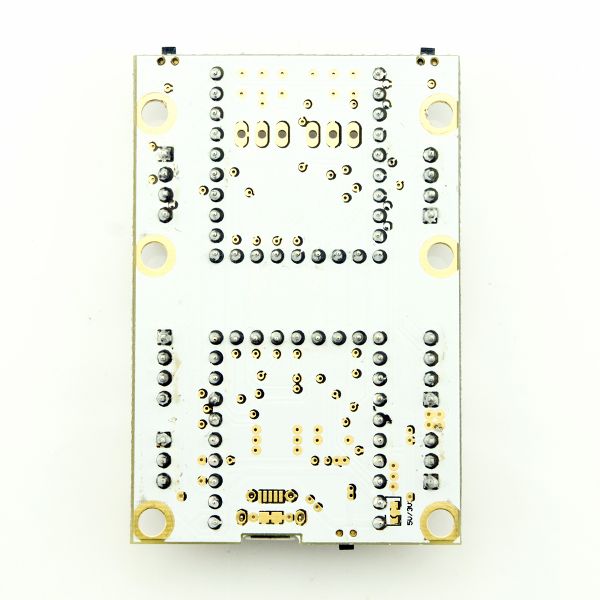
Back

Microduino-Cube-V1 Back

Video