“Microduino-BT”的版本间的差异
853387039@qq.com(讨论 | 贡献) (→APP) |
|||
| (未显示3个用户的4个中间版本) | |||
| 第51行: | 第51行: | ||
===Main Components=== | ===Main Components=== | ||
*cc2541_datasheet:'''[[File:Cc2541.pdf]]''' | *cc2541_datasheet:'''[[File:Cc2541.pdf]]''' | ||
| + | ===Android APP=== | ||
| + | *APP Installation package:'''[[File:BT APP.zip]]''' | ||
| + | *APP Source:https://github.com/iascchen/android-microduino | ||
==Development== | ==Development== | ||
| 第65行: | 第68行: | ||
**No check | **No check | ||
**Data bit 8 | **Data bit 8 | ||
| − | **Stop | + | **Stop bit |
===Use PC to Debug=== | ===Use PC to Debug=== | ||
| 第87行: | 第90行: | ||
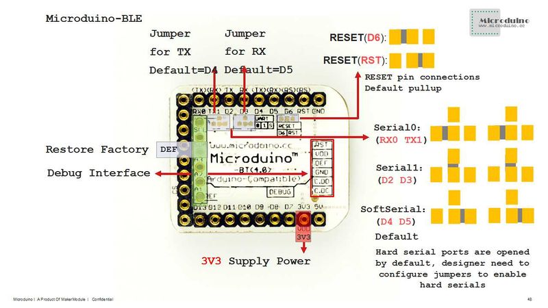
*If it keeps using the default jumper (RX0、TX1): | *If it keeps using the default jumper (RX0、TX1): | ||
**Unplug the Microduino Shield BT4.0 during downloading the program; | **Unplug the Microduino Shield BT4.0 during downloading the program; | ||
| − | *If you want to change the jumper cables to meet your requirement, you need to cut the connection between two intermediate of the pad and RX0/TX1, and then connect them to D2, D3(or | + | *If you want to change the jumper cables to meet your requirement, you need to cut the connection between two intermediate of the pad and RX0/TX1, and then connect them to D2, D3 (or D9, D10). |
**If it needs to change the jumper, you can change the serial connection of Microduino Shield BT4.0 and Microduino Core from "TX-RX0、RX-TX1" to: | **If it needs to change the jumper, you can change the serial connection of Microduino Shield BT4.0 and Microduino Core from "TX-RX0、RX-TX1" to: | ||
| − | ***TX- | + | ***TX-D2, RX-D3 (For Core+'s Serial1) |
| − | ***TX- | + | ***TX-D9, RX-D10 (you can adopt SoftwareSerial libray to solve the problem) |
===Pin Description=== | ===Pin Description=== | ||
| 第149行: | 第152行: | ||
==History== | ==History== | ||
| − | *On June 5, | + | *On July, 28, 2014, the module scheme was cancelled. The new BT version adopts CC25541 chip, supporting iBeacons mode. For the old version, you can refer to [[Microduino-【BT】]]. |
| − | *On May | + | *On June 5, 2014, the second proofing was finished, changing its name to <nowiki>Microduino-[BT]</nowiki> and addomg the third optional serial port—UART1. It is divided into two versions—version 2.1, a module used for HM09 and 4.0 version, a module used for HM10. |
| + | *On 10, May, 2013, the board design was finished. | ||
| + | |||
|- | |- | ||
| | | | ||
| + | |||
==Pictures== | ==Pictures== | ||
[[file:Microduino-【BT】-t.jpg|thumb|600px|center|Microduino BT 4.0 Front]] | [[file:Microduino-【BT】-t.jpg|thumb|600px|center|Microduino BT 4.0 Front]] | ||
2015年10月15日 (四) 08:30的最新版本
| Language | English |
|---|
|
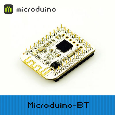
Microduino-BT is a BLE serial transparent transmission module based on CC2541 chip. It is custom-made for U-shaped 27PIN standard interface of Microduino. The old version can refer to Microduino-【BT】. 目录Features
Specification
**After connection:
DocumentEagle PCB 文件:Microduino-BT Shield.zip Support AT instruction configuration/control: 文件:Microduino-BLE.pdf Main Components
Android APP
DevelopmentSerial Port Communication Requirements
Use PC to Debug
Use USBTTL and Core to Download and Debug
Pin Description
ApplicationProgram DownloadProgram test: 文件:BLE debug uart1.zip,文件:BLE LightBlue time.zip Serial Port Debug Shield BT4.0 by CoreUSB
Have serial debugging of BT module by uart1 of Core+
How to Connect Two Microduino-BT ModulesIntercommunication between Two Microduino-BT ModulesMicroduino BT Serial port Transmits Data to IOS DeviceNote:If you use Android device to debug, you need to make sure the system should be version 4.3 or higher so that Microduino-BT can be detected.A simple test of Microduino-Shield BT4.0
FQA
BuyHistory
| |||||||||||||||||||
Pictures文件:Microduino-【BT】-t.jpg Microduino BT 4.0 Front 文件:Microduino-【BT】-b.jpg Microduino BT 4.0 Back Video |


