“Lesson 6--Microduino "Breathing Light"”的版本间的差异
853387039@qq.com(讨论 | 贡献) (→Program) |
|||
| (未显示2个用户的3个中间版本) | |||
| 第4行: | 第4行: | ||
| | | | ||
==Objective== | ==Objective== | ||
| − | + | In the last two lessons we used external devices (a button and a potentiometer) to generate PWM to control the LED. From Lesson 1, we also learned how to turned an LED on and off using software. But how would we go about controlling an LED's brightness through PWM using software only? This lesson will teach you how to implement an LED "Breathing Light". | |
| − | This lesson will | ||
==Equipment== | ==Equipment== | ||
| 第11行: | 第10行: | ||
*'''[[Microduino-FT232R]]''' | *'''[[Microduino-FT232R]]''' | ||
*Other hardware equipment | *Other hardware equipment | ||
| − | ** | + | **1x Box of breadboard jumper wires |
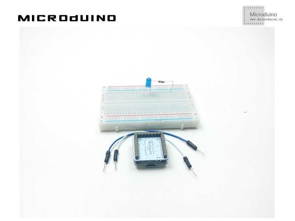
| − | **Breadboard | + | **1x Breadboard |
| − | **LED | + | **1x LED |
| − | **220Ω resistor | + | **1x 220Ω resistor |
| − | **USB Data cable | + | **1x USB Data cable |
| − | == | + | |
| + | [[File:lesson6All.jpg|600px|center|thumb]] | ||
| + | |||
| + | ==Experiment Schematic== | ||
[[File:lesson 6-schematic.jpg|600px|center|thumb]] | [[File:lesson 6-schematic.jpg|600px|center|thumb]] | ||
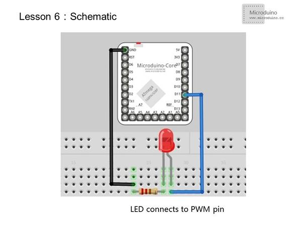
| − | + | The schematic above uses a high level connection. Since we want the LED to be more than just on and off, we still need to connect the anode to a Microduino PWM I/O port. Using a low level connection achieves the same result. | |
==Program== | ==Program== | ||
| 第44行: | 第46行: | ||
} | } | ||
</source> | </source> | ||
| − | + | This program uses for loops, which allows for convenient control of the brightness of the LEDs. | |
==Result== | ==Result== | ||
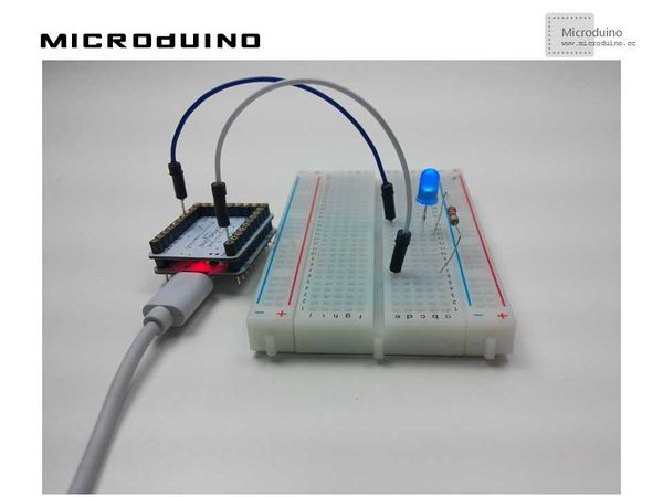
| − | LED | + | LED gradually goes from off to on, then off. It then repeats. |
| + | |||
| + | [[File:lesson6Result.jpg|600px|center|thumb]] | ||
==Video== | ==Video== | ||
| + | http://v.youku.com/v_show/id_XNzA5OTk3MTU2.html | ||
|} | |} | ||
2015年7月13日 (一) 08:16的最新版本
| Language | English |
|---|
ObjectiveIn the last two lessons we used external devices (a button and a potentiometer) to generate PWM to control the LED. From Lesson 1, we also learned how to turned an LED on and off using software. But how would we go about controlling an LED's brightness through PWM using software only? This lesson will teach you how to implement an LED "Breathing Light". Equipment
Experiment SchematicThe schematic above uses a high level connection. Since we want the LED to be more than just on and off, we still need to connect the anode to a Microduino PWM I/O port. Using a low level connection achieves the same result. Programint ledPin=11;//D3、D5、D6、D9、D10、D11 is Microduino PWM I/O output port
void setup()
{
pinMode(ledPin,OUTPUT);
}
void loop()
{
for(int fadeValue=0;fadeValue<=255;fadeValue+=5)
//Increase PWM value, control the LED brightness by adjusting the value of fadeValue.
{
analogWrite(ledPin,fadeValue); //Write the brightness value to LED.
delay(30); //Keep the current brightness 30ms.
}
for(int fadeValue=255;fadeValue>=0;fadeValue-=5)
//Decrease PWM value,control the LED brightness by adjusting the value of fadeValue.
{
analogWrite(ledPin,fadeValue); //Write the brightness value to LED.
delay(30); //Keep the current brightness 30ms.
}
}
This program uses for loops, which allows for convenient control of the brightness of the LEDs. ResultLED gradually goes from off to on, then off. It then repeats. Video |


