“仪表盘”的版本间的差异
(→设备) |
(→调试) |
||
| (未显示同一用户的1个中间版本) | |||
| 第21行: | 第21行: | ||
==程序== | ==程序== | ||
| − | https://github.com/Microduino/Microduino_Tutorials/tree/master/Microduino_Processing/MicroduinoDashboard | + | [https://github.com/Microduino/Microduino_Tutorials/tree/master/Microduino_Processing/MicroduinoDashboard MicroduinoDashboard] |
| − | https://github.com/Microduino/Microduino_Tutorials/tree/master/Microduino_Processing/ProcessingDashboard | + | [https://github.com/Microduino/Microduino_Tutorials/tree/master/Microduino_Processing/ProcessingDashboard ProcessingDashboard] |
==调试== | ==调试== | ||
| 第30行: | 第30行: | ||
[[File:processingDashboardConnectionDiagram.jpg|600px|center|thumb]] | [[File:processingDashboardConnectionDiagram.jpg|600px|center|thumb]] | ||
| − | + | 下载这个HMC5883L的库函数:[https://github.com/manifestinteractive/arduino/tree/master/Libraries/HMC5883L HMC5883L] | |
步骤二:解释一下代码: | 步骤二:解释一下代码: | ||
2014年10月29日 (三) 07:30的最新版本
| Language | English |
|---|
目的本教程将教大家如何用processing实现一个仪表盘显示Microduino感应的磁场变化。 设备
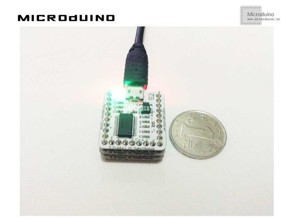
原理图直接使用Microduino-10DOF上的HMC5883L磁场强度传感器 程序调试步骤一:按着原理图搭建硬件环境,像这样: 下载这个HMC5883L的库函数:HMC5883L 步骤二:解释一下代码: 本例需要两端的代码,Processing端和Microduino端 Microduino: 在setup()中主要是初始化HMC5883L 在loop()中计算出周围磁感应的角度 //Output()用来输出计算出的角度到串口 // Output the data down the serial port.
void Output(int RoundDegreeInt)
{
//Serial.println();
Serial.println(RoundDegreeInt);
delay(150);
}
//得到第一个串口的数据. myPort = new Serial(this, Serial.list()[0], 9600); //drawCube()中的以下代码用来的到串口的数据 while (myPort.available() > 0) {
myString = myPort.readStringUntil(lf);
if (myString != null) {
//print(myString); // Prints String
angle=float(myString); // Converts and prints float
println(angle);
}
}
函数说明: //绘制仪表盘的中心点 buildpoint() //绘制仪表盘和指针刻度 builddashboard() //接收串口数据并绘制中心点 drawCube() //绘制整体的仪表盘 drawCube1()
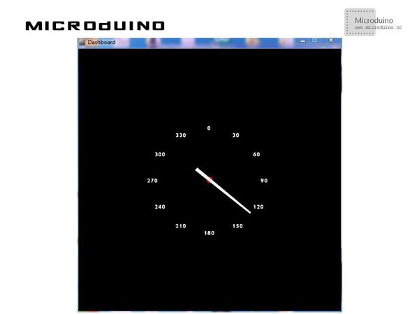
步骤四:运行后,用一块磁铁改变一下磁场,看看指针是否变化。 结果屏幕上会显示一个指南针,指针会随着磁场走,像这样:
视频 |

