“Lesson 4--Microduino "LED Brightness and PWM"”的版本间的差异
Jasonsheng(讨论 | 贡献) (Created page with "{| style="width: 800px;" |- | ==Objective== LED has only two states on and off in other three experiment, now through button realize LED brightness light gradually and gradual...") |
|||
| (未显示4个用户的6个中间版本) | |||
| 第1行: | 第1行: | ||
| + | {{Language|第四课--按钮PWM控制LED亮度}} | ||
{| style="width: 800px;" | {| style="width: 800px;" | ||
|- | |- | ||
| | | | ||
==Objective== | ==Objective== | ||
| − | LED | + | In the previous three lessons, the LED was either on or off. In this lesson, you will learn how to control an LED's brightness using a button and PWM. PWM stands for pulse width modulation. The circuit adjusts the ratio of digital signals ("0", "1") to create a certain brightness. For example, if there are more 1's (HIGH), then the LED seems brighter. |
| − | |||
| − | |||
| − | |||
| − | |||
==Equipment== | ==Equipment== | ||
| 第13行: | 第10行: | ||
*'''[[Microduino-FT232R]]''' | *'''[[Microduino-FT232R]]''' | ||
*Other hardware equipment | *Other hardware equipment | ||
| − | ** | + | **1x Box of breadboard jumper wires |
| − | **Breadboard | + | **1x Breadboard |
| − | **LED | + | **1x LED |
| − | **220ohm resistor | + | **1x 220ohm resistor |
| − | **Button | + | **1x Button |
| − | **USB Data cable | + | **1x USB Data cable |
| − | == | + | [[File:lesson3All1.jpg|600px|center|thumb]] |
| − | [[File: | + | |
| − | + | ==Experiment Schematic== | |
| − | + | [[File:pwm schematic.jpg|600px|center|thumb]] | |
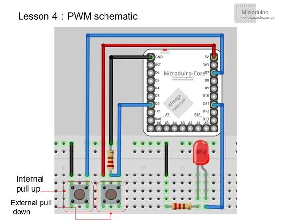
| + | One button is connected using internal pull-up and the other using external pull-down. They are then connected to I/O ports D0~D13. For the [[Microduino-Core]], only D3, D5, D6, D9, D10, and D11 support PWM, so the user must connect the LED to one of those ports. | ||
| + | |||
| + | [[File:lesson3Setup1.jpg|600px|center|thumb]] | ||
==Program== | ==Program== | ||
| 第33行: | 第33行: | ||
pinMode(2,INPUT); | pinMode(2,INPUT); | ||
pinMode(7,INPUT_PULLUP);//Set to internal pull-up | pinMode(7,INPUT_PULLUP);//Set to internal pull-up | ||
| − | pinMode(11,OUTPUT);// | + | pinMode(11,OUTPUT);//PWM must use I/O ports 3、5、11、9、10、11 |
} | } | ||
| 第60行: | 第60行: | ||
} | } | ||
</source> | </source> | ||
| − | === | + | ===analogWrite() usage=== |
| − | * | + | *Usage:Writes the simulation value to the specified pin |
| − | * | + | *Parameters:analogWrite(pin, val) |
| + | **pin: Microduino I/O port number | ||
| + | **val: values from 0 to 255 | ||
==Result== | ==Result== | ||
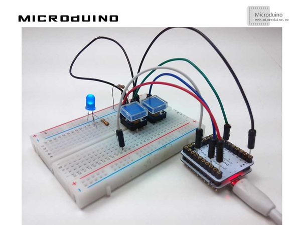
| − | Left button | + | Left button increases LED brightness and right button decreases LED brightness. |
| + | |||
| + | [[File:lesson3Result1.jpg|600px|center|thumb]] | ||
| + | |||
==Video== | ==Video== | ||
|} | |} | ||
2015年7月13日 (一) 03:02的最新版本
| Language | English |
|---|
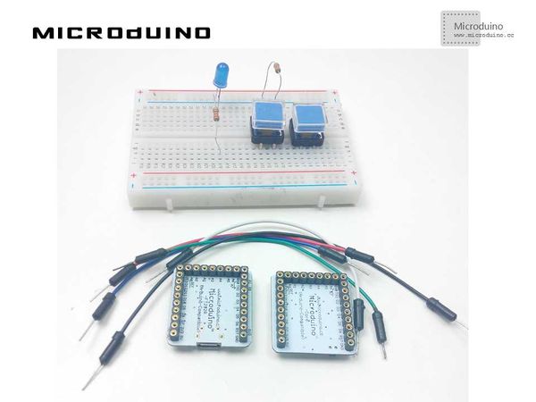
目录ObjectiveIn the previous three lessons, the LED was either on or off. In this lesson, you will learn how to control an LED's brightness using a button and PWM. PWM stands for pulse width modulation. The circuit adjusts the ratio of digital signals ("0", "1") to create a certain brightness. For example, if there are more 1's (HIGH), then the LED seems brighter. Equipment
Experiment SchematicOne button is connected using internal pull-up and the other using external pull-down. They are then connected to I/O ports D0~D13. For the Microduino-Core, only D3, D5, D6, D9, D10, and D11 support PWM, so the user must connect the LED to one of those ports. Programint n=0;
void setup ()
{
pinMode(2,INPUT);
pinMode(7,INPUT_PULLUP);//Set to internal pull-up
pinMode(11,OUTPUT);//PWM must use I/O ports 3、5、11、9、10、11
}
void loop()
{
int up =digitalRead(2); //Read port 2's state
int down = digitalRead(7); //Read port 7's state
if (up==HIGH)
{
n=n+5;
if (n>=255) {
n=255;
} //The max limitation is 255
analogWrite(11,n); //Using PWM control the output of port 11, the range of the variable n is 0-255
delay (300);
}
if (down==LOW)
{
n=n-5;
if (n<=0) {
n=0;
}
analogWrite(11,n); //Using PWM control the output of port 11, the range of the variable n is 0-255
delay (300);
}
}
analogWrite() usage
ResultLeft button increases LED brightness and right button decreases LED brightness. Video |


