“Microduino-GPS”的版本间的差异
(→Test Microduino NEO-6M using FT232 and core module) |
(→FQA) |
||
| (未显示2个用户的13个中间版本) | |||
| 第4行: | 第4行: | ||
| | | | ||
[[file:Microduino-NEO-rect.jpg|400px|thumb|right|Microduino-NEO]] | [[file:Microduino-NEO-rect.jpg|400px|thumb|right|Microduino-NEO]] | ||
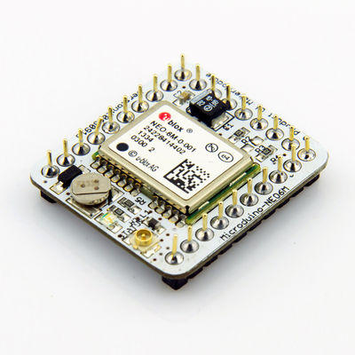
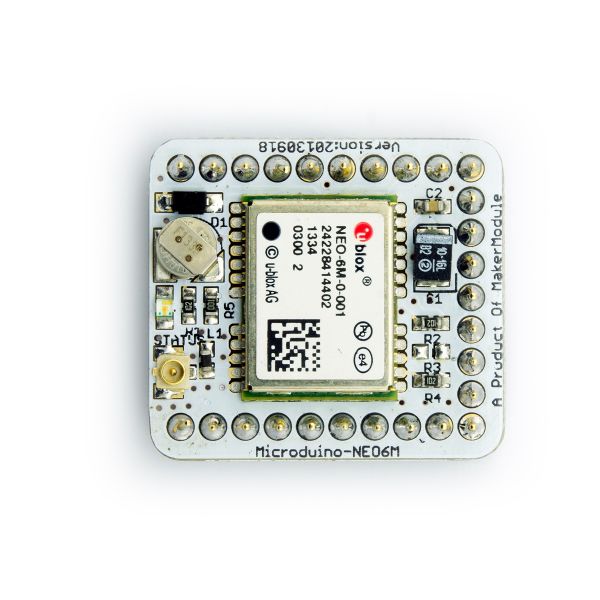
| − | + | This probably the most beautiful GPS module you've seen, adopting UBLOX NEO-6M as it core with high sensitivity and update rate up to 5Hz. Besides, it owns a mini ceramic antenna with IPEX interface as well as a rechargeable backup battery. | |
| − | |||
==Feature== | ==Feature== | ||
| − | *High | + | *High sensitivity |
| − | *Update rate up to | + | *Update rate up to 5Hz |
| − | * | + | *Own a powerful PC support: u-center; |
| − | *PPS | + | *With PPS indicator, it is very convenient for us to judge the current status of the module; |
| − | * | + | *Own a built-in rechargeable backup battery(support warm or hot start); |
*Small, cheap, stackable and open; | *Small, cheap, stackable and open; | ||
| − | *Open | + | *Open hardware circuit design and Arduino compatible programming development environment; |
| − | * | + | *Uniform Microduino interface standard and rich peripheral modules, capable of having a fast and flexible connection and extension with other modules and sensors in accord with Microduino interface standard; |
*Easy to be integrated to pegboards with a 2.45-pitch female header connector interface. | *Easy to be integrated to pegboards with a 2.45-pitch female header connector interface. | ||
| − | |||
|- | |- | ||
| | | | ||
| 第22行: | 第20行: | ||
==Specifications== | ==Specifications== | ||
*Communication protocol: | *Communication protocol: | ||
| − | **Microduino NEO-6M module adopts NMEA-0183 protocol to output GPS data and | + | **Microduino NEO-6M module adopts NMEA-0183 protocol to output GPS data and is capable of configuring modules through UBX protocol. |
*Receiving characteristics | *Receiving characteristics | ||
| 第40行: | 第38行: | ||
*Note: | *Note: | ||
| − | **Cold | + | **Cold start refers to restarting when the history GPS information saved by the module all gets lost.(Equal to both of the main power supply and the backup battery run out of power.) |
| − | **Warm | + | **Warm start refers to restarting when the module the current satellite information disaccords with the history GPS receiving information saved by the module. |
| − | **Hot | + | **Hot start means restarting when the history GPS receiving information is saved by the module and keeps consistent with the current visible satellite information. |
*Interface characteristics | *Interface characteristics | ||
| 第49行: | 第47行: | ||
***Microduino NEO-6M module supports several kinds of baud rate:4800,9600,38400(defult),57600; | ***Microduino NEO-6M module supports several kinds of baud rate:4800,9600,38400(defult),57600; | ||
| − | * Set baud rate | + | * Set baud rate according to two resistors of the module (R3 and R4. 1k recommended): |
{|class="wikitable" | {|class="wikitable" | ||
! rowspan="1" | R3 || R4 || Protocol || Baud rate | ! rowspan="1" | R3 || R4 || Protocol || Baud rate | ||
| 第66行: | 第64行: | ||
! rowspan="1" | GPS Module Pin || Microduino Pin|| Function | ! rowspan="1" | GPS Module Pin || Microduino Pin|| Function | ||
|- | |- | ||
| − | | TX || RX0(or D2) || | + | | TX || RX0(or D2) || Sending pin of the module serial port (TTL level), capable of connecting to microcontroller's RXD |
|- | |- | ||
| − | | RX || TX1(or D3) || | + | | RX || TX1(or D3) || Receiving pin of the module serial port (TTL level), capable of connecting to microcontroller's MCU TXD |
|} | |} | ||
| 第81行: | 第79行: | ||
===Main components=== | ===Main components=== | ||
*GPS module:UBLOX NEO-6M:'''[[File:NEO-6 DataSheet (GPS.G6-HW-09005).pdf]]''' | *GPS module:UBLOX NEO-6M:'''[[File:NEO-6 DataSheet (GPS.G6-HW-09005).pdf]]''' | ||
| − | * | + | *Supercapacitor:XH414H '''[[File:XH414H.pdf]]''' |
*NMEA-0183 protocol: '''[[File:NMEA-0183 CN.pdf]]''','''[[File:NMEA-0183 EN.pdf]]''' | *NMEA-0183 protocol: '''[[File:NMEA-0183 CN.pdf]]''','''[[File:NMEA-0183 EN.pdf]]''' | ||
| 第99行: | 第97行: | ||
===Use FT232R and Core to download and debug=== | ===Use FT232R and Core to download and debug=== | ||
*If you keep using the default jumper (RX0、TX1): | *If you keep using the default jumper (RX0、TX1): | ||
| − | **Please unplug the Microduino NEO-6M during download | + | **Please unplug the Microduino NEO-6M during the program download; |
| − | *If you want to change the | + | *If you want to change the jumpers to meet your requirement:Just cut the connection between the middle of two groups of pads and RX0/TX1,then connect them to D2, D3. |
**If you change the jumper, you need to change the serial connection between Microduino NEO-6M and Microduino Core from "TX-RX0、RX-TX1" to: | **If you change the jumper, you need to change the serial connection between Microduino NEO-6M and Microduino Core from "TX-RX0、RX-TX1" to: | ||
***TX-D2、RX-D3 (For Core+'s Serial port) | ***TX-D2、RX-D3 (For Core+'s Serial port) | ||
| 第122行: | 第120行: | ||
===PPS Status indicator=== | ===PPS Status indicator=== | ||
*The indicator is connected to the TIMEPULSE port of the UBLOX NEO-6M module and the output characteristics of the port can be set by the program; | *The indicator is connected to the TIMEPULSE port of the UBLOX NEO-6M module and the output characteristics of the port can be set by the program; | ||
| − | *The PPS | + | *The PPS indicating light has two status under the default condition(without program setup): |
**Always keeping on means that the indicator has started work but failed to achieve positioning; | **Always keeping on means that the indicator has started work but failed to achieve positioning; | ||
**Keeping flashing means the module has achieved positioning. | **Keeping flashing means the module has achieved positioning. | ||
| − | *By the PPS indicator, it is very easy for us | + | *By the PPS indicator, it is very easy for us to judge the current status of the module. |
==Application== | ==Application== | ||
| 第150行: | 第148行: | ||
There are two connection methods: | There are two connection methods: | ||
1. Use the default pin (RX0、TX1): | 1. Use the default pin (RX0、TX1): | ||
| − | *You need the Microduino FT232R module to connect the PC, but can't superimpose the FT232R, NEO-6M and Core module directly. Because the FT232 and NEO-6M has the same RX/TX defination and position on board, but the normal serial communication should be cross | + | *You need the Microduino FT232R module to connect the PC, but can't superimpose the FT232R, NEO-6M and Core module directly. Because the FT232 and NEO-6M has the same RX/TX defination and position on board, but the normal serial communication should be cross connected with RX/TX. |
| − | ** | + | **Stack up the FT232 and microduino core, then conect them to PC with microUSB to download program; |
| − | ** | + | **Use jumpers to cross connect the RX0/TX1 of FT232 and NEO-6M, that is to connect the RX0 of NEO-6M to the TX1 of FT232, and the TX1 of NEO-6M to RX0 of FT232. |
| − | **Connect the 3V3 pin of NEO-6M module to 3V3 pin of FT232 | + | **Connect the 3V3 pin of NEO-6M module to 3V3 pin of FT232 and GND to GND for modules' power supply. |
[[File:Neo-6m debugging.jpg|thumb|400px|center|crossover configuration]] | [[File:Neo-6m debugging.jpg|thumb|400px|center|crossover configuration]] | ||
2. Use the changed jumper mode | 2. Use the changed jumper mode | ||
| − | If you have changed the jumper as | + | If you have changed the jumper as it describes above, you can stack up FT232, NEO-6M and Core module together, then connect to PC for debugging. |
====Use u-center configuration module to update rage==== | ====Use u-center configuration module to update rage==== | ||
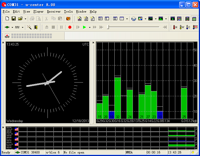
| − | *Firstly, place the Microduino NEO-6M into an open area, and then | + | *Firstly, place the Microduino NEO-6M into an open area, and then connect it to PC through Microduino FT232R; |
*Start "u-center" software: | *Start "u-center" software: | ||
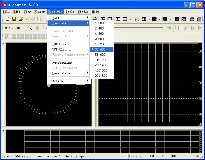
| − | **Set the baud | + | **Set the baud rate firstly:Menu:“Receiver”-“Baudrate”-“38400”; |
[[File:U-center 01.jpg|thumb|703px|center|set baud rate]] | [[File:U-center 01.jpg|thumb|703px|center|set baud rate]] | ||
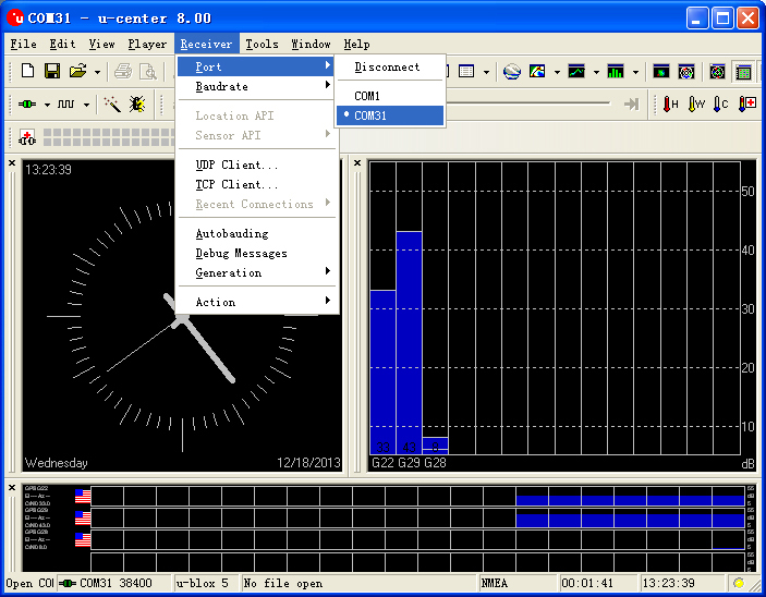
**Open the serial to start the communication:Menu:“Receiver”-“Port”- choose the port that Microduino FT232R using. | **Open the serial to start the communication:Menu:“Receiver”-“Port”- choose the port that Microduino FT232R using. | ||
| 第171行: | 第169行: | ||
*Update rate | *Update rate | ||
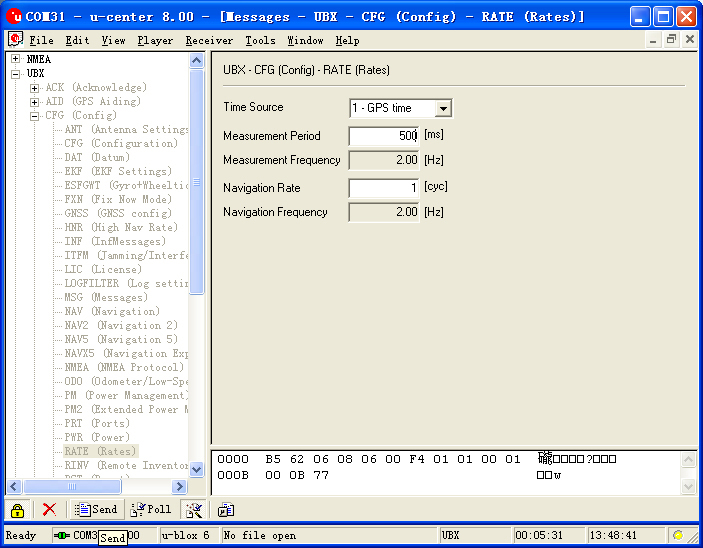
**Open menu:“View”-“Messages View”,display the "Messages" window; | **Open menu:“View”-“Messages View”,display the "Messages" window; | ||
| − | **Open“UBX”-“CFG(Config)”-“RATE(Rates) | + | **Open“UBX”-“CFG(Config)”-“RATE(Rates)”,supposing you need 2HZ update rate, you just need to set the "Measurement Period" to 500ms; |
| − | **After | + | **After the configuration,just click the "Send" button on the bottom of the left and send the configuration to Microduino NEO-6M module. If the data update rate turns faster on other information window, that means the setup is successful. |
[[File:U-center 04.jpg|thumb|703px|center|Configure window]] | [[File:U-center 04.jpg|thumb|703px|center|Configure window]] | ||
| − | == | + | ==FQA== |
| + | *This module's issue, you can find the solution in wiki. Please refers to the wiki to test this module. | ||
| + | *If using the core and GPS module, what’s the power consumption? | ||
| + | **'''Make sure 3.3V with 200mA.''' | ||
| + | |||
| + | ==Buy== | ||
==History== | ==History== | ||
2015年1月3日 (六) 03:51的最新版本
| Language | English |
|---|
|
This probably the most beautiful GPS module you've seen, adopting UBLOX NEO-6M as it core with high sensitivity and update rate up to 5Hz. Besides, it owns a mini ceramic antenna with IPEX interface as well as a rechargeable backup battery. 目录Feature
| |||||||||||||||||||||||||||||
Specifications
Pin Description
文件:NEO6M-Pinout-2.jpg Microduino-NEO6M-Pinout 文件:NEO6M-Pinout-1.jpg Microduino-NEO6M-Pinout DocumentEagle PCB 文件:Microduino-NEO6M.zip
Main components
Development
Use PC to debug
Use FT232R and Core to download and debug
Arduino library and support package
How to use the library
PPS Status indicator
ApplicationDownload programTest Program:文件:Program Test NEO-6M.zip Test Microduino NEO-6M
Test Mocroduino NEO-6M using PCConnection methodThere are two connection methods: 1. Use the default pin (RX0、TX1):
文件:Neo-6m debugging.jpg crossover configuration 2. Use the changed jumper mode If you have changed the jumper as it describes above, you can stack up FT232, NEO-6M and Core module together, then connect to PC for debugging. Use u-center configuration module to update rage
FQA
BuyHistoryPicture
Video |
