“Microduino-CoreSTM32/zh”的版本间的差异

来自Microduino Wikipedia
跳转至: 导航搜索
 
(未显示5个用户的31个中间版本)
第3行: 第3行:
 
|-
 
|-
 
|
 
|
[[file:Microduino-core -rect.jpg|400px|thumb|right|Microduino-Core]]
+
[[file:Microduino- CoreSTM32 -rect.jpg|400px|thumb|right|Microduino- CoreSTM32]]
 +
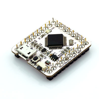
Microduino-CoreSTM32是Microduino系列的核心模块之一,采用 STM32F103CBT6芯片的ARM开发板。'''[[Microduino-CoreSTM32]]'''是一个开放源码硬件与[http://leaflabs.com/docs/hardware/maple-mini.html Maple Mini]兼容,可利用 Microduino 扩展模块和其他电子元件、模块、传感器,做出很多丰富有趣的互动作品。
  
'''[[Microduino-CoreSTM32]]''' is one of core modules of Microduino series, '''[[Microduino-CoreSTM32]]''' is an open source hardware and [http://leaflabs.com/docs/hardware/maple-mini.html Maple Mini] compatible. It is an 32-bit ARM Cortex-M3 development board, based on STMicroelectronics' STM32F103CBT6 chip.
+
==特色==
 +
* 小巧、便宜、堆叠、开放。
 +
* 开源的硬件电路设计,与Arduino相似的编程开发环境程;
 +
* Microduino- CoreSTM32可使用Microduino-USBTTL模块灵活烧入[http://static.leaflabs.com/pub/leaflabs/maple-bootloader/maple_mini_boot.bin bootloader]
 +
* 统一的 Microduino 接口规范,和丰富的外围模块,可方便、灵活的与其他符合 Microduino 接口规范的模块、传感器进行快速的连接和扩展;
 +
* 2.54间距的排母接口方便集成到洞洞板。
 +
|-
 +
|
  
 +
==规格==
 +
===电气规格===
 +
*微控制器:STM32F103CBT6
 +
*速度:72MHz的
 +
*工作电压:5V
 +
*核心电压:3.3V
 +
*Flash:128KB
 +
* SRAM:20KB
 +
===引脚规格===
 +
*数字I/ O引脚: 0,1,2,3,4,5,6,7,8,9,10,11,12,13,14(A0),15(A1),16(A2),17(A3),18(SDA),19(SCL),20(A6),21(A7)
 +
*模拟输入引脚:A0(ADC12_IN0),A1(ADC12_IN1),A2(ADC12_IN2),A3(ADC12_IN3),10(ADC12_IN4),13(ADC12_IN5),12(ADC12_IN6),11(ADC12_IN7),A6(ADC12_IN8),A7(ADC12_IN9)
 +
*串口:
 +
**Serial RX0和TX1。用于接收(RX)和发送(TX)TTL串行数据。
 +
**Serial1 D2(RX3)和D3(TX3)。用于接收(RX)和发送(TX)TTL串行数据。
 +
* 硬件PWM: 0,1,4,11,12,14(A0),15(A1),16(A2),17(A3),18(SDA),19(SCL),20(A6),21(A7)
 +
* SPI:D10(SPI1_NSS)、D11(SPI1_MOSI)、D12(SPI1_MISO)、D13(SPI1_SCK);
 +
*IIC:18(SDA)、19(SCL) ;
 +
*每个I/O口都具有中断功能。
  
==Features==
+
:[[file:Microduino-Core STM-PinoutBig.png|800px|thumb|center|Microduino-Core STM-Pinout]]
* Small, Stackable, Strong
+
:[[file:Microduino-Core STM-Pinout1Big.png|800px|thumb|center|Microduino-Core STM-Pinout]]
* Open source hardware, using the same development environment as Arduino IDE
+
:[[file:Microduino-Core STM-Pinout2Big.png|800px|thumb|center|Microduino-Core STM-Pinout]]
* Using the U-Shape 27-pin interface (UPin-27), the standard interface of Microduino series
 
  
Microduino modules and sensors can be easily stacked and extended through it
+
==文档==
* Delivered ready to plug in.
+
*Microduino- CoreSTM32 中使用的主要元器件
* 2.54mm (0.1 inch) pin pitch, compatible to bread board and hole board
+
** MCU: '''[[media: STM32F103CBT6.pdf| STM32F103CBT6]]'''
  
|-
+
==开发==
|
+
===设置Microduino-CoreSTM32开发环境(1)===
==Specifications==
+
*使用 Maple IDE开发环境:Microduino使用与Arduino相似的IDE 语言的开发环境。玩家可以使用 Maple IDE 与 Flash 或 Processing 等软件,配合其他电子元件、模块、传感器,利用 Microduino 做出很多丰富有趣的互动作品。
* Microcontroller: STM32F103CBT6
+
*配置Maple IDE开发环境请参考'''[[Microduino-CoreSTM32 Maple驱动安装]]'''
* Speed: 72MHz
+
*向Microduino-CoreSTM32下载程序,直接使用Microduino-CoreSTM32上的USB接口,不需要使用[[Microduino-USBTTL/zh]]模块,只有烧写bootLoader才使用到[[Microduino-USBTTL/zh]],默认是有bootloader,可以不用烧写。
* Operating Voltage: 5V
 
* Core Voltage: 3.3V
 
* Flash: 128KB
 
* SRAM:  20KB
 
* Digital I/O Pins: 14 (of which 6 provide PWM output with D3,D5,D6,D9,D10 and D11)
 
* Analog Input Pins: 8 (2 more comparing to Arduino Uno)
 
* DC Current per I/O Pin: 40 mA
 
* DC Current:  50 mA
 
* Serial: 0 (RX) and 1 (TX). Used to receive (RX) and transmit (TX) TTL serial data.
 
* External Interrupts: 2 and 3. These pins can be configured to trigger an interrupt on a low value, a rising or falling edge, or a change in value. See the attachInterrupt() function for details.
 
* PWM: 3, 5, 6, 9, 10, and 11. Provide 8-bit PWM output with the analogWrite() function.
 
* SPI: 10 (SS), 11 (MOSI), 12 (MISO), 13 (SCK). These pins support SPI communication using the SPI
 
  
library.
+
===编程Microduino-CoreSTM32(1)===
* TWI: A4 or SDA pin and A5 or SCL pin. Support TWI communication using the Wire library.
 
* AREF. Reference voltage for the analog inputs. Used with analogReference().
 
* Flash Memory 32 KB (ATmega328P) of which 0.5 KB used by bootloader
 
* SRAM 2 KB (ATmega328P)
 
* EEPROM 1 KB (ATmega328P)
 
* Clock Speed 16MHz(5V) / 8Mhz(3.3V)
 
  
 +
*请确保你已经安装Microduino-CoreSTM32的驱动程序
 +
*需要的硬件设备:Microduino-CoreSTM32、USB数据线一根
 +
*需要软件设备:Maple ID
 +
'''[[开始你的Micoduino-CoreSTM32]]'''
  
|-
+
===设置Microduino-CoreSTM32开发环境(2)===
|
+
*使用 Keil uVision开发环境:对Microduino-CoreSTM32开发也可以使用keil软件。此环境不仅可以使用C语言编程还可以用汇编语言编程,具有方便易用的集成环境、强大的软件仿真调试工具。Keil提供了包括C编译器、宏汇编、链接器、库管理和一个功能强大的仿真调试器等在内的完整开发方案,通过一个集成开发环境(μVision)将这些部分组合在一起。
 +
*配置Keil uVision开发环境请参考'''[[Microduino-CoreSTM32 Keil开发环境的配置]]'''
 +
*向Microduino-CoreSTM32下载程序,可以直接使用Microduino-CoreSTM32上的USB接口,但若要进行在线断点调试,需要用到另一模块Microduino-CoreSTMDEBUGE,即stlink.可以将两个模块直接进行叠加,使用Microduino-CoreSTMDEBUGE模块上的USB接口连接电脑进行程序下载。
  
==Documents==
+
===编程Microduino-CoreSTM32(2)===
* '''[[Microduino-Core]]''' Eagle source file 【'''[[media:Microduino-Core.zip|download]]'''】
 
* '''[[Microduino-Core]]''' main chips and devices
 
** MCU: '''[[media:ATmega168PA328P.pdf|ATmega168PA/328P]]'''
 
|-
 
|
 
  
==Development==
+
*请确保你已经安装STLINK驱动
* Microduino Arduino IDE Configuration
+
*需要的硬件设备:Microduino-CoreSTM32、Microduino-CoreSTMDEBUGE、USB数据线一根
** 1. Install Arduino IDE: Microduino use the same IDE as Arduino, please download Arduino IDE from 【'''[http://arduino.cc/en/Main/Software Arduino IDE official]'''】 and install it in your disk. (if you already have it, just skip this step). Please check Arduino IDE details from 【'''[http://arduino.cc/en/Reference/HomePage Reference]'''】 and 【'''[http://arduino.cc/en/Tutorial/HomePage Workshop]'''】.
+
*需要软件设备:Keil uVision5
** 2. Patch Microduino package: Please download Microduino package for Arduino IDE from 【'''[[media:Microduino-hardware.zip|download]]'''】, and unzip is to {Your Arduino Install Driectory}/hardware directory.
+
'''[[STM32 Keil开发环境的实验]]'''
** Microduino Arduino IDE Reference workshop: 【'''[[Arduino IDE Microduino Configuration]]'''】.
 
** 3. Programming: To upload program to Microduino-Core/Core+ through Arduino IDE, designers are recommended to use '''[[Microduino-FT232R]]''' module.
 
** 4. Enjoy your Microduino journey!
 
  
* Burn Microduino BootLoader
 
** Bootloader burning is necessary if designers want to update Microduino-Core/Core+ firmware by themselves, designers can leaverage Arduino Uno or another burned Microduino-Core/Core+ to make a new one.
 
** Microduino bootloader workshop: 【'''[[Burn Bootloader to Microduino-Core/Core+ with an Arduino]]'''】.
 
** Bootloader is specified for different Microduino-Core/Core+ configurations, correct one must be selected during burning.
 
** Initial bootloader is designed for ATmegaX8 series optiboot, which occupies only 512 bytes flash.
 
|-
 
|
 
  
==Applications==
+
===烧写 Microduino-CoreSTM32  BootLoader===
* room-Microduino
 
* obdii-Microduino
 
* pilot-Microduino
 
* green-Microduino
 
* music-Microduino
 
|-
 
|
 
  
==Buy==
+
*如果玩家的Microduino-CoreSTM32的bootLoader坏了,则需要利用[[Microduino-USBTTL/zh]]给Microduino- CoreSTM32重新烧写 bootloader,玩家可以参考教程 '''[[你知道怎么用Microduino-USBTTL向Microduino- CoreSTM32烧写bootloader]]'''
* Buy '''[http://www.microduino.cc/Modules/Microdoino%20Core%20Modules/Microdoino-Core Microduino-Core]'''
 
  
|-
+
==应用==
|
+
[[Microduino CoreSTM32教程]]
==History==
 
*2012/12/16: Published Microduino-Core patch for Arduino IDE
 
*2012/11/18: Optimized the first formal release, finalized Miroduino-Core configuration
 
*2012/11/06: Beta version.
 
  
|-
 
|
 
==Pictures==
 
:[[file:Microduino-Core-t.JPG|thumb|600px|center|Microduino-core Front]]
 
<br style="clear: left"/>
 
:[[file:Microduino-Core-b.JPG|thumb|600px|center|Microduino-core Back]]
 
<br style="clear: left"/>
 
:[[file:Microduino-Core-3d.jpg|thumb|600px|center|Microduino-core 3D model]]
 
<br style="clear: left"/>
 
:[[file:Microduino-Core-Upin27.jpg|thumb|600px|center|Microduino-core Upin27 model]]
 
<br style="clear: left"/>
 
 
|}
 
|}

2017年4月25日 (二) 05:45的最新版本

Language English
Microduino- CoreSTM32

Microduino-CoreSTM32是Microduino系列的核心模块之一,采用 STM32F103CBT6芯片的ARM开发板。Microduino-CoreSTM32是一个开放源码硬件与Maple Mini兼容,可利用 Microduino 扩展模块和其他电子元件、模块、传感器,做出很多丰富有趣的互动作品。

特色

  • 小巧、便宜、堆叠、开放。
  • 开源的硬件电路设计,与Arduino相似的编程开发环境程;
  • Microduino- CoreSTM32可使用Microduino-USBTTL模块灵活烧入bootloader
  • 统一的 Microduino 接口规范,和丰富的外围模块,可方便、灵活的与其他符合 Microduino 接口规范的模块、传感器进行快速的连接和扩展;
  • 2.54间距的排母接口方便集成到洞洞板。

规格

电气规格

  • 微控制器:STM32F103CBT6
  • 速度:72MHz的
  • 工作电压:5V
  • 核心电压:3.3V
  • Flash:128KB
  • SRAM:20KB

引脚规格

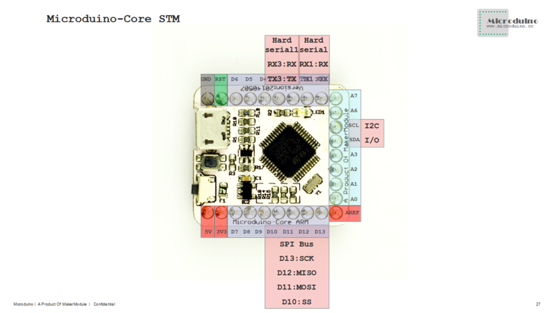
  • 数字I/ O引脚: 0,1,2,3,4,5,6,7,8,9,10,11,12,13,14(A0),15(A1),16(A2),17(A3),18(SDA),19(SCL),20(A6),21(A7)
  • 模拟输入引脚:A0(ADC12_IN0),A1(ADC12_IN1),A2(ADC12_IN2),A3(ADC12_IN3),10(ADC12_IN4),13(ADC12_IN5),12(ADC12_IN6),11(ADC12_IN7),A6(ADC12_IN8),A7(ADC12_IN9)
  • 串口:
    • Serial RX0和TX1。用于接收(RX)和发送(TX)TTL串行数据。
    • Serial1 D2(RX3)和D3(TX3)。用于接收(RX)和发送(TX)TTL串行数据。
  • 硬件PWM: 0,1,4,11,12,14(A0),15(A1),16(A2),17(A3),18(SDA),19(SCL),20(A6),21(A7)
  • SPI:D10(SPI1_NSS)、D11(SPI1_MOSI)、D12(SPI1_MISO)、D13(SPI1_SCK);
  • IIC:18(SDA)、19(SCL) ;
  • 每个I/O口都具有中断功能。
Microduino-Core STM-Pinout

文档

开发

设置Microduino-CoreSTM32开发环境(1)

  • 使用 Maple IDE开发环境:Microduino使用与Arduino相似的IDE 语言的开发环境。玩家可以使用 Maple IDE 与 Flash 或 Processing 等软件,配合其他电子元件、模块、传感器,利用 Microduino 做出很多丰富有趣的互动作品。
  • 配置Maple IDE开发环境请参考Microduino-CoreSTM32 Maple驱动安装
  • 向Microduino-CoreSTM32下载程序,直接使用Microduino-CoreSTM32上的USB接口,不需要使用Microduino-USBTTL/zh模块,只有烧写bootLoader才使用到Microduino-USBTTL/zh,默认是有bootloader,可以不用烧写。

编程Microduino-CoreSTM32(1)

  • 请确保你已经安装Microduino-CoreSTM32的驱动程序
  • 需要的硬件设备:Microduino-CoreSTM32、USB数据线一根
  • 需要软件设备:Maple ID

开始你的Micoduino-CoreSTM32

设置Microduino-CoreSTM32开发环境(2)

  • 使用 Keil uVision开发环境:对Microduino-CoreSTM32开发也可以使用keil软件。此环境不仅可以使用C语言编程还可以用汇编语言编程,具有方便易用的集成环境、强大的软件仿真调试工具。Keil提供了包括C编译器、宏汇编、链接器、库管理和一个功能强大的仿真调试器等在内的完整开发方案,通过一个集成开发环境(μVision)将这些部分组合在一起。
  • 配置Keil uVision开发环境请参考Microduino-CoreSTM32 Keil开发环境的配置
  • 向Microduino-CoreSTM32下载程序,可以直接使用Microduino-CoreSTM32上的USB接口,但若要进行在线断点调试,需要用到另一模块Microduino-CoreSTMDEBUGE,即stlink.可以将两个模块直接进行叠加,使用Microduino-CoreSTMDEBUGE模块上的USB接口连接电脑进行程序下载。

编程Microduino-CoreSTM32(2)

  • 请确保你已经安装STLINK驱动
  • 需要的硬件设备:Microduino-CoreSTM32、Microduino-CoreSTMDEBUGE、USB数据线一根
  • 需要软件设备:Keil uVision5

STM32 Keil开发环境的实验


烧写 Microduino-CoreSTM32 BootLoader

应用

Microduino CoreSTM32教程