“Microduino-Core”的版本间的差异
(→Specifications) |
714982818@qq.com(讨论 | 贡献) |
||
| (未显示5个用户的14个中间版本) | |||
| 第1行: | 第1行: | ||
| + | {{Language|Microduino-Core}} | ||
{| style="width: 800px;" | {| style="width: 800px;" | ||
|- | |- | ||
| 第138行: | 第139行: | ||
* Microcontroller: ATmega328P/ATmega168PA | * Microcontroller: ATmega328P/ATmega168PA | ||
* Operating Voltage: 5V/3.3V | * Operating Voltage: 5V/3.3V | ||
| − | |||
* Digital I/O Pins: 14 (of which 6 provide PWM output with D3,D5,D6,D9,D10 and D11) | * Digital I/O Pins: 14 (of which 6 provide PWM output with D3,D5,D6,D9,D10 and D11) | ||
* Analog Input Pins: 8 (2 more comparing to Arduino Uno) | * Analog Input Pins: 8 (2 more comparing to Arduino Uno) | ||
| 第194行: | 第194行: | ||
|} | |} | ||
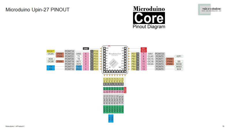
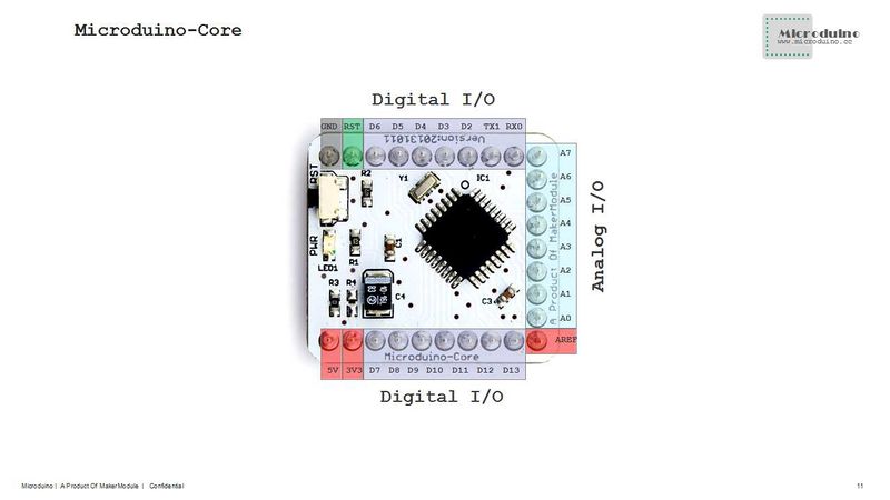
| + | :[[file:Microduino-Core-Pinout.jpg|800px|thumb|center|Microduino-Core-Pinout]] | ||
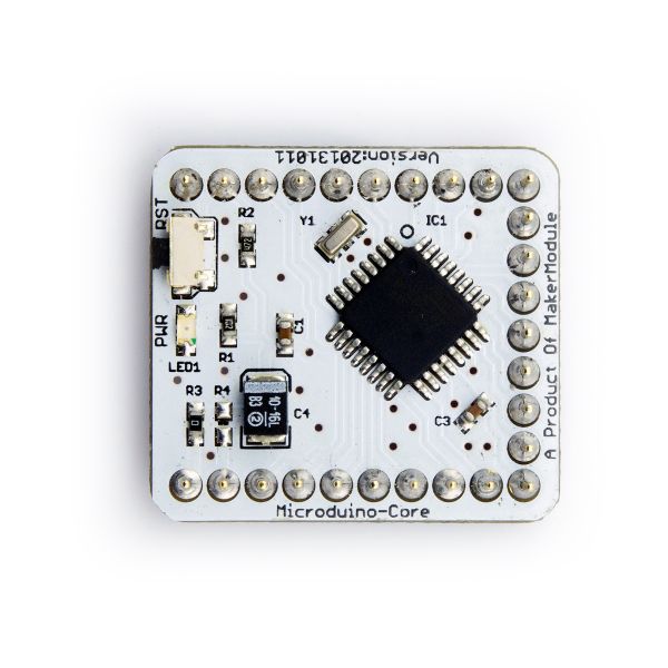
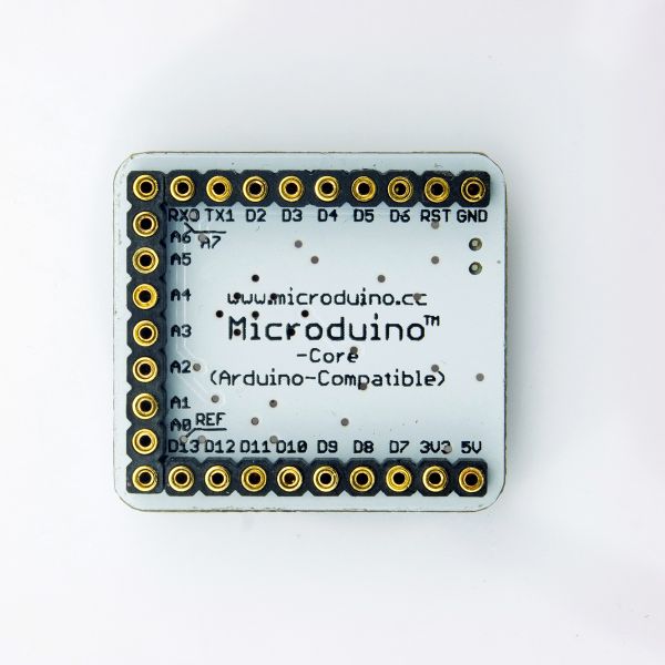
:[[file:Microduino-Core-Pinout1.jpg|800px|thumb|center|Microduino-Core-Pinout]] | :[[file:Microduino-Core-Pinout1.jpg|800px|thumb|center|Microduino-Core-Pinout]] | ||
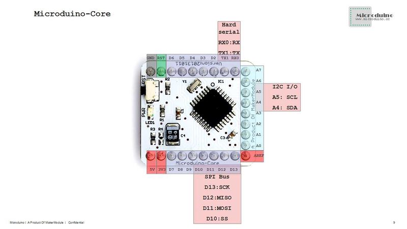
:[[file:Microduino-Core-Pinout2.jpg|800px|thumb|center|Microduino-Core-Pinout]] | :[[file:Microduino-Core-Pinout2.jpg|800px|thumb|center|Microduino-Core-Pinout]] | ||
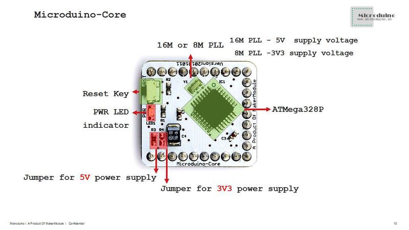
:[[file:Microduino-Core-Pinout3.jpg|800px|thumb|center|Microduino-Core-Pinout]] | :[[file:Microduino-Core-Pinout3.jpg|800px|thumb|center|Microduino-Core-Pinout]] | ||
| − | + | ||
| − | |||
| − | |||
|- | |- | ||
| 第205行: | 第204行: | ||
==Documents== | ==Documents== | ||
| − | |||
| − | |||
| − | |||
| − | |||
| − | |||
| − | |||
* '''[[Microduino-Core]]''' Eagle source file 【'''[[media:Microduino-Core.zip|download]]'''】 | * '''[[Microduino-Core]]''' Eagle source file 【'''[[media:Microduino-Core.zip|download]]'''】 | ||
* '''[[Microduino-Core]]''' main chips and devices | * '''[[Microduino-Core]]''' main chips and devices | ||
** MCU: '''[[media:ATmega168PA328P.pdf|ATmega168PA/328P]]''' | ** MCU: '''[[media:ATmega168PA328P.pdf|ATmega168PA/328P]]''' | ||
| − | |||
| − | |||
|- | |- | ||
| | | | ||
==Development== | ==Development== | ||
| − | + | '''[[Microduino Getting start]]''' | |
| − | |||
| − | |||
| − | |||
| − | |||
| − | |||
* Burn Microduino BootLoader | * Burn Microduino BootLoader | ||
| 第232行: | 第218行: | ||
** Bootloader is specified for different Microduino-Core/Core+ configurations, correct one must be selected during burning. | ** Bootloader is specified for different Microduino-Core/Core+ configurations, correct one must be selected during burning. | ||
** Initial bootloader is designed for ATmegaX8 series optiboot, which occupies only 512 bytes flash. | ** Initial bootloader is designed for ATmegaX8 series optiboot, which occupies only 512 bytes flash. | ||
| + | * How to download program to Microduino through Arduino:'''[[Media:Arduino-Miccroduino-e.pdf|Download program to Microduino through Arduino ]]''' | ||
|- | |- | ||
| | | | ||
| 第243行: | 第230行: | ||
|- | |- | ||
| | | | ||
| + | |||
| + | ==FAQ== | ||
| + | *How to use the Microduino? | ||
| + | **Install Arduino IDE | ||
| + | **Download Arduino IDE Microduino hardware support package:https://github.com/wasdpkj/Microduino-IDE/tree/master/arduino-1.0.6-windows/hardware/Microduino | ||
| + | **Write the code in Arduino IDE,recommend use release 1.0 or upper | ||
| + | **Connect the hardware,core/core+ and USBTTL module, select the correct board type and download the program | ||
| + | **If download failed, please check the hardware connection firstly, and then reset the board, try again | ||
| + | **If still failure, you can search the failure information in internet, maybe need burn the bootloader. How to burn the bootloader, please refer to following link:【'''[[Burn Bootloader to Microduino-Core/Core+ with an Arduino]]'''】 | ||
| + | *Do you have 3.3V version board? | ||
| + | **So far no. | ||
| + | *Does Core has PWM pin? | ||
| + | **Core supports six PWM output, that is I/O port 3,5,6,9,10 and 11. Core+ supports six PWM output, that is 7,8,9,10,22 and 23 | ||
==Buy== | ==Buy== | ||
| 第262行: | 第262行: | ||
<br style="clear: left"/> | <br style="clear: left"/> | ||
:[[file:Microduino-Core-3d.jpg|thumb|600px|center|Microduino-core 3D model]] | :[[file:Microduino-Core-3d.jpg|thumb|600px|center|Microduino-core 3D model]] | ||
| + | <br style="clear: left"/> | ||
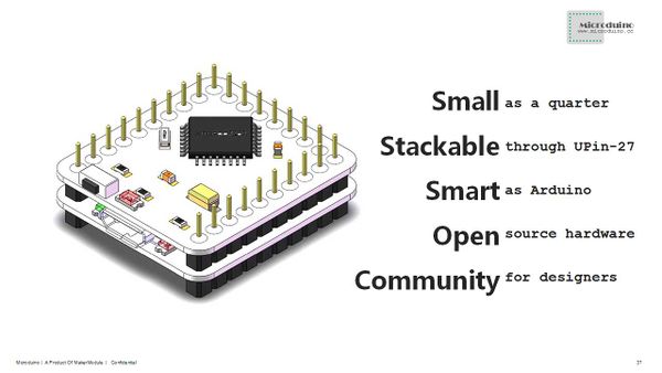
| + | :[[file:Microduino-Core-Upin27.jpg|thumb|600px|center|Microduino-core Upin27 model]] | ||
<br style="clear: left"/> | <br style="clear: left"/> | ||
|} | |} | ||
2014年12月5日 (五) 08:58的最新版本
| Language | English |
|---|
|
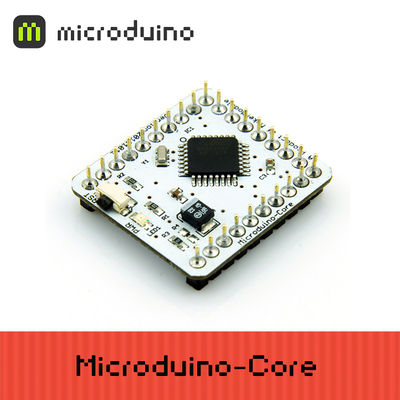
Microduino-Core is one of core modules of Microduino series, Microduino-Core is an open source hardware and Arduino Uno compatible. It is an 8-bit microcontroller development board, based on Atmel ATmega328P/ATmega168PA series. Comparing to Arduino Uno, Microduino-Core is featured by:
Microduino uses the same development environment as Arduino IDE, designers can use the Arduino IDE, Processing on Microduino for idea realization, prototype development and low volume production. Microduino uses optiboot for bootloader, it takes less Flash than Arduino default engine and optimizes program uploading. Currently, there are 4 different configurations for Microduino-Core modules:
Different configurations in frequency and supply voltage:
| |||||||||||||||||||||||||||||||||||||||||||
目录Core vs Core+
| |||||||||||||||||||||||||||||||||||||||||||
Features
Microduino modules and sensors can be easily stacked and extended through it
| |||||||||||||||||||||||||||||||||||||||||||
Specifications
library.
| |||||||||||||||||||||||||||||||||||||||||||
Documents
| |||||||||||||||||||||||||||||||||||||||||||
Development
| |||||||||||||||||||||||||||||||||||||||||||
Applications
| |||||||||||||||||||||||||||||||||||||||||||
FAQ
Buy
| |||||||||||||||||||||||||||||||||||||||||||
History
| |||||||||||||||||||||||||||||||||||||||||||
Pictures
|
