|
|
| (未显示2个用户的4个中间版本) |
| 第7行: |
第7行: |
| | | | |
| | ==设备== | | ==设备== |
| − | *'''[[Microduino-Core]]''' | + | *'''[[Microduino-Core/zh]]''' |
| − | *'''[[Microduino-FT232R]]''' | + | *'''[[Microduino-USBTTL/zh]]''' |
| | *其他硬件设备 | | *其他硬件设备 |
| | **面包板跳线 一盒 | | **面包板跳线 一盒 |
| 第14行: |
第14行: |
| | **8*8点阵LED 一个 | | **8*8点阵LED 一个 |
| | **74HC595 2个 | | **74HC595 2个 |
| − | **喇叭1个
| |
| − | **1uF电容两个(可以选择0.1uF~10uF)
| |
| | **USB数据连接线 一根 | | **USB数据连接线 一根 |
| | | | |
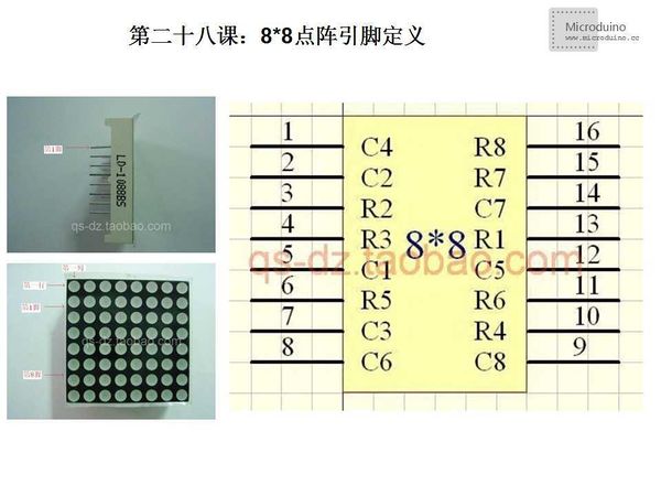
| | '''8*8点阵LED的型号是:LD-1088BS,其引脚定义如下图:''' | | '''8*8点阵LED的型号是:LD-1088BS,其引脚定义如下图:''' |
| | [[File:第二十八课-8_8点阵引脚定义.jpg|600px|center|thumb]] | | [[File:第二十八课-8_8点阵引脚定义.jpg|600px|center|thumb]] |
| − |
| |
| − |
| |
| | | | |
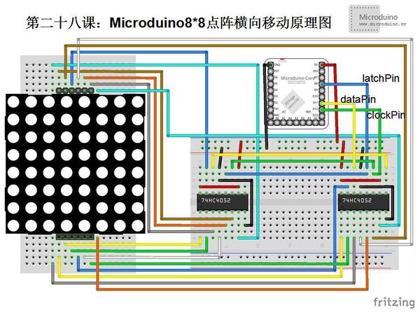
| | ==原理图== | | ==原理图== |
| 第73行: |
第69行: |
| | | | |
| | ==程序== | | ==程序== |
| − | <source lang="cpp">
| |
| − |
| |
| − |
| |
| − | //Pin 连接到 74HC595的ST_CP
| |
| − | int latchPin = 8;
| |
| − | //Pin 连接到 74HC595的SH_CP
| |
| − | int clockPin = 12;
| |
| − | //Pin 连接到 74HC595的DS
| |
| − | int dataPin = 11;
| |
| − |
| |
| − | //设定时间
| |
| − | unsigned long time;
| |
| − |
| |
| − | //掩盖行定义
| |
| − | byte masks[8]={
| |
| − | B01111111,B10111111,B11011111,B11101111,B11110111,B11111011,B11111101,B11111110};
| |
| − |
| |
| − |
| |
| − | //笑脸横向移动定义
| |
| − | byte rows[4][8]={
| |
| − | {
| |
| − | B00111100,B01000010,B10100101,B10000001,B10100101,B10011001,B01000010,B00111100 }
| |
| − | ,
| |
| − | {
| |
| − | B00011110,B00100001,B11010010,B11000000,B11010100,B11001100,B00100001,B00011110 }
| |
| − | ,
| |
| − | {
| |
| − | B00001111,B10010000,B11101001,B01100000,B01101010,B01100110,B10010000,B00001111 }
| |
| − | ,
| |
| − | {
| |
| − | B10000111,B01001000,B11110100,B00110000,B00110101,B00110011,B01001000,B10000111 }
| |
| − | };
| |
| − |
| |
| − |
| |
| − | void setup() {
| |
| − | //波特率为9600,用于调试
| |
| − | Serial.begin(9600);
| |
| − | //设置 latchpin 为 output
| |
| − | pinMode(latchPin, OUTPUT);
| |
| − |
| |
| − | }
| |
| − |
| |
| − | void loop() {
| |
| − |
| |
| − | //笑脸横向移动
| |
| − | for(int j=0;j<4;j++) {
| |
| − | unsigned long startTime = millis();
| |
| − | for (unsigned long elapsed=0; elapsed < 1000; elapsed = millis() - startTime) {//持续显示600ms
| |
| − | for(int i=0;i<8;i++) {
| |
| − | digitalWrite(latchPin, 0);
| |
| − | shiftOut(dataPin, clockPin, masks[i]); //mask(col)
| |
| − | shiftOut(dataPin, clockPin, rows[j][i]); //row
| |
| − | digitalWrite(latchPin, 1);
| |
| − | }
| |
| − | }
| |
| − | //time=0;
| |
| − |
| |
| − | }
| |
| − | }
| |
| − |
| |
| − | void shiftOut(int myDataPin, int myClockPin, byte myDataOut) {
| |
| − | // This shifts 8 bits out MSB first,
| |
| − | //on the rising edge of the clock,
| |
| − | //clock idles low
| |
| − |
| |
| − | //internal function setup
| |
| − | int i=0;
| |
| − | int pinState;
| |
| − | pinMode(myClockPin, OUTPUT);
| |
| − | pinMode(myDataPin, OUTPUT);
| |
| − |
| |
| − | //clear everything out just in case to
| |
| − | //prepare shift register for bit shifting
| |
| − | digitalWrite(myDataPin, 0);
| |
| − | digitalWrite(myClockPin, 0);
| |
| − |
| |
| − | //for each bit in the byte myDataOut�
| |
| − | //NOTICE THAT WE ARE COUNTING DOWN in our for loop
| |
| − | //This means that %00000001 or "1" will go through such
| |
| − | //that it will be pin Q0 that lights.
| |
| − | for (i=7; i>=0; i--) {
| |
| − | digitalWrite(myClockPin, 0);
| |
| − |
| |
| − | //if the value passed to myDataOut and a bitmask result
| |
| − | // true then... so if we are at i=6 and our value is
| |
| − | // %11010100 it would the code compares it to %01000000
| |
| − | // and proceeds to set pinState to 1.
| |
| − | if ( myDataOut & (1<<i) ) {
| |
| − | pinState= 1;
| |
| − | }
| |
| − | else {
| |
| − | pinState= 0;
| |
| − | }
| |
| − |
| |
| − | //Sets the pin to HIGH or LOW depending on pinState
| |
| − | digitalWrite(myDataPin, pinState);
| |
| − | //register shifts bits on upstroke of clock pin
| |
| − | digitalWrite(myClockPin, 1);
| |
| − | //zero the data pin after shift to prevent bleed through
| |
| − | digitalWrite(myDataPin, 0);
| |
| − | }
| |
| − |
| |
| − | //stop shifting
| |
| − | digitalWrite(myClockPin, 0);
| |
| − | }
| |
| − |
| |
| − |
| |
| − |
| |
| | | | |
| | + | [https://github.com/Microduino/Microduino_Tutorials/tree/master/Microduino_Advanced/Microduino8_8LateralMovement Microduino8_8LateralMovement] |
| | | | |
| | | | |
| − | </source>
| + | 在程序中定义byte rows[4][8]的四个横向移动动作 |
| | | | |
| | ==调试== | | ==调试== |


