“Microduino-Cube-S1”的版本间的差异
(→Features) |
|||
| (未显示同一用户的8个中间版本) | |||
| 第1行: | 第1行: | ||
| − | Microduino-Cube-S1 | + | {{Language | Microduino-Cube-S1}} |
{| style="width: 800px;" | {| style="width: 800px;" | ||
|- | |- | ||
| 第5行: | 第5行: | ||
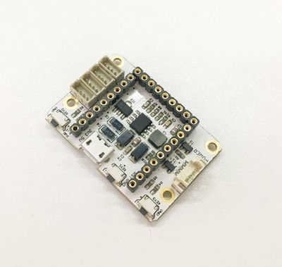
[[File:Microduino-S1-rect.jpg|400px|thumb|right|Microduino-Cube-S1]] | [[File:Microduino-S1-rect.jpg|400px|thumb|right|Microduino-Cube-S1]] | ||
==Features== | ==Features== | ||
| − | * | + | *Compatible with the pin of Arduino Uno; |
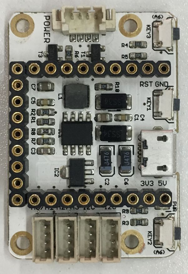
| − | * | + | *Uniform Microduino interface standard and rich peripheral modules, capable of having a fast and flexible connection and extension with other modules and sensors meeting Microduino interface standard; |
| − | + | *Onboard analog button and sensor interface; | |
| − | *Onboard analog | ||
==Specification== | ==Specification== | ||
| − | *Electrical | + | *Electrical specification |
**MicroUSB power supply; | **MicroUSB power supply; | ||
| − | **3.3V | + | **3.3V constant voltage; |
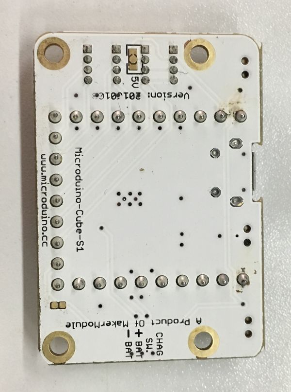
| − | **Select the 5V or 3.3V power via PWR jumper | + | **Select the 5V or 3.3V power via PWR jumper(The default voltage is 3.3V); |
| − | **Onboard power supply ( | + | **Onboard power supply indicator(5V and PWR) ; |
| − | * | + | *Extension |
**Onboard reset button; | **Onboard reset button; | ||
| − | **OLED | + | **The fixed OLED base; |
| − | **Two serial ports, | + | **Two serial ports including (RX0,TX0)and (D2,D3); |
**Two IIC interfaces; | **Two IIC interfaces; | ||
| − | ***Two | + | ***Two analog button interfaces connected to A7; |
| − | ** | + | **The sensor interface can be selected and combined through jumpers: |
| − | ***PWR, A3, GND, PWR or PWR, A3, GND, GND or PWR, D6, GND, PWR or PWR, D6, GND,GND. | + | ***PWR, A3, GND, PWR or PWR, A3, GND, GND or PWR, D6, GND, PWR or PWR, D6, GND,GND (Users can make the connection as they like). |
[[file:Microduino-Cube-S1-Pinout1.jpg|800px|thumb|center|Microduino-Cube-S1]] | [[file:Microduino-Cube-S1-Pinout1.jpg|800px|thumb|center|Microduino-Cube-S1]] | ||
| 第31行: | 第30行: | ||
==Document== | ==Document== | ||
| − | Eagle PCB | + | Eagle PCB: '''[[File:Microduino-Cube-S1.zip]]''' |
| − | Main | + | |
| − | *3.3V | + | Main Component: |
| + | *3.3V Voltage Stablizing chip LP2985: '''[[File:LP2985.pdf]]''' | ||
==Development== | ==Development== | ||
| − | + | Microduino-Cube-S1 is capable of having a fast and flexible connection and extension with other modules and sensors meeting Microduino interface standard, achieving specific function. | |
[[file:Microduino-Cube-S1-Pinout4.jpg|800px|thumb|center|Microduino-Cube-S1]] | [[file:Microduino-Cube-S1-Pinout4.jpg|800px|thumb|center|Microduino-Cube-S1]] | ||
==Application== | ==Application== | ||
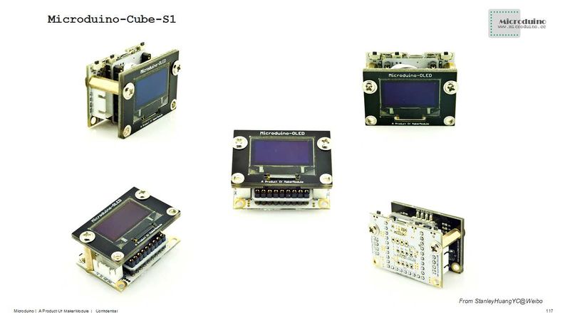
| − | *You can download | + | *You can download Microduino test program, which together with OLED to test the function of Microduino-Cube-S1's two analog buttons. Just as follows: |
| − | * | + | https://github.com/Microduino/Microduino_Tutorials/commit/b0e0fe74269ee0f6a886d8fa8db497ec57cc4073 |
| − | * | + | *Hardware Needed:Microduino FT232R, Microduino Core, Microduino-Cube-S1 and Microduino OLED; |
| − | *Open the example program in IDE, select the board "Microduino Core (Atmega328P@16M,5V)", download directly; | + | *Software Needed:Microduino example program (Arduino part) and Arduino IDE(Version 1.0 and higher); |
| − | *After download, | + | *Open the example program in IDE, select the board "Microduino Core (Atmega328P@16M,5V)", then download directly; |
| − | **Press the left button | + | *After the download, "No button is pressed " is displayed on the OLED, |
| − | **Press the right button | + | **Press the left button and "Press the left button" will come out, meaning the left button gets pressed; |
| − | ** | + | **Press the right button and "Press the right button" will be displayed on the OLED, meaning the right button is pressed; |
| − | + | **When no button is pressed, "No button is pressed " will be displayed, which is just like the initial state. | |
==Bug== | ==Bug== | ||
2014年8月22日 (五) 02:54的最新版本
| Language | English |
|---|
目录Features
Specification
文件:Microduino-Cube-S1-Pinout1.jpg Microduino-Cube-S1 文件:Microduino-Cube-S1-Pinout2.jpg Microduino-Cube-S1-Pinout 文件:Microduino-Cube-S1-Pinout3.jpg Microduino-Cube-S1-Pinout DocumentEagle PCB: 文件:Microduino-Cube-S1.zip Main Component:
DevelopmentMicroduino-Cube-S1 is capable of having a fast and flexible connection and extension with other modules and sensors meeting Microduino interface standard, achieving specific function. Application
https://github.com/Microduino/Microduino_Tutorials/commit/b0e0fe74269ee0f6a886d8fa8db497ec57cc4073
BugHistoryPictureFrontBackVideo |


