“Microduino-FT232R”的版本间的差异
(→Pictures) |
(→Specifications) |
||
| (未显示2个用户的6个中间版本) | |||
| 第1行: | 第1行: | ||
| + | {{Language|Microduino-FT232R}} | ||
{| style="width: 800px;" | {| style="width: 800px;" | ||
|- | |- | ||
| | | | ||
| − | [[file: | + | [[file:Microduino-ft232r-rect.jpg|400px|thumb|right|Microduino-FT232R]] |
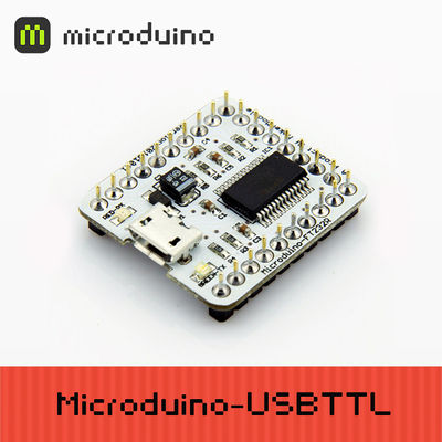
'''[[Microduino-FT232R]]''' is a USB to serial UART interface module, it is based on FDTI FT232RL chip (Arduino embedded driver). '''[[Microduino-FT232R]]''' can be stacked with '''[[Microduino-Core]]''' or '''[[Microduino-Core+]]''', enable Microduino core modules communicating with PC. | '''[[Microduino-FT232R]]''' is a USB to serial UART interface module, it is based on FDTI FT232RL chip (Arduino embedded driver). '''[[Microduino-FT232R]]''' can be stacked with '''[[Microduino-Core]]''' or '''[[Microduino-Core+]]''', enable Microduino core modules communicating with PC. | ||
| 第24行: | 第25行: | ||
* Single chip USB to asynchronous serial data transfer interface. | * Single chip USB to asynchronous serial data transfer interface. | ||
* Entire USB protocol handled on the chip - No USB-specific firmware programming required. | * Entire USB protocol handled on the chip - No USB-specific firmware programming required. | ||
| − | * UART interface support for 7 or 8 data bits, 1 or 2 stop bits and odd / even / mark / space / no parity. | + | * UART interface support for 7 or 8 data bits, 1 or 2 stop bits and odd/even/mark/space/no parity. |
| − | * Fully assisted hardware or X-On / X-Off software handshaking. | + | * Fully assisted hardware or X-On/X-Off software handshaking. |
| − | * Data transfer rates from 300 baud to 3 Megabaud (RS422 / RS485 and at TTL levels) and 300 baud to 1 Megabaud (RS232). | + | * Data transfer rates from 300 baud to 3 Megabaud (RS422/RS485 and at TTL levels) and 300 baud to 1 Megabaud (RS232). |
* Auto transmit buffer control for RS485 applications. | * Auto transmit buffer control for RS485 applications. | ||
* Transmit and receive LED drive signals. | * Transmit and receive LED drive signals. | ||
| 第34行: | 第35行: | ||
* Integrated 1024 bit internal EEPROM for I/O configuration and storing USB VID, PID, serial number and product description strings. | * Integrated 1024 bit internal EEPROM for I/O configuration and storing USB VID, PID, serial number and product description strings. | ||
* Device supplied preprogrammed with unique USB serial number. | * Device supplied preprogrammed with unique USB serial number. | ||
| − | * Support for USB suspend / resume. | + | * Support for USB suspend/resume. |
* Support for bus powered, self powered, and high-power bus powered USB configurations. | * Support for bus powered, self powered, and high-power bus powered USB configurations. | ||
* Integrated 3.3V level converter for USB I/O . | * Integrated 3.3V level converter for USB I/O . | ||
* Integrated level converter on UART and CBUS for interfacing to 5V - 1.8V Logic. | * Integrated level converter on UART and CBUS for interfacing to 5V - 1.8V Logic. | ||
| − | * True 5V / 3.3V / 2.8V / 1.8V CMOS drive output and TTL input. | + | * True 5V/3.3V/2.8V/1.8V CMOS drive output and TTL input. |
* High I/O pin output drive option. | * High I/O pin output drive option. | ||
* Integrated USB resistors. | * Integrated USB resistors. | ||
| 第46行: | 第47行: | ||
* USB bulk transfer mode. | * USB bulk transfer mode. | ||
* 3.3V to 5.25V Single Supply Operation. | * 3.3V to 5.25V Single Supply Operation. | ||
| − | * UHCI / OHCI / EHCI host controller compatible. | + | * UHCI/OHCI/EHCI host controller compatible. |
* USB 2.0 Full Speed compatible. | * USB 2.0 Full Speed compatible. | ||
| − | :[[file:Micromodule-FT232R-Pinout. | + | :[[file:Micromodule-FT232R-Pinout.jpg|800px|thumb|center|Microduino-FT232R-Pinout]] |
|- | |- | ||
| 第55行: | 第56行: | ||
==Documents== | ==Documents== | ||
| − | + | ||
| − | |||
| − | |||
| − | |||
| − | |||
* '''[[Microduino-FT232R]]''' Eagle source file 【'''[[media:Microduino-FT232R.zip|download]]'''】 | * '''[[Microduino-FT232R]]''' Eagle source file 【'''[[media:Microduino-FT232R.zip|download]]'''】 | ||
* '''[[Microduino-FT232R]]''' main chips and devices | * '''[[Microduino-FT232R]]''' main chips and devices | ||
** Main chip: '''[[media:DS_FT232R.pdf|Datasheet of FT232R]]''' | ** Main chip: '''[[media:DS_FT232R.pdf|Datasheet of FT232R]]''' | ||
| − | ** Micro USB: '''[[media:MicroUSB. | + | ** Micro USB: '''[[media:MicroUSB.doc|MicroUSB]]''' |
** Diode: '''[[media:MBR0520.pdf|MBR0520]]''' | ** Diode: '''[[media:MBR0520.pdf|MBR0520]]''' | ||
| 第100行: | 第97行: | ||
==Pictures== | ==Pictures== | ||
| − | [[file:Micromodule-FT232R- | + | [[file:Micromodule-FT232R-t.jpg|thumb|600px|center|Micromodule FT232R Front]] |
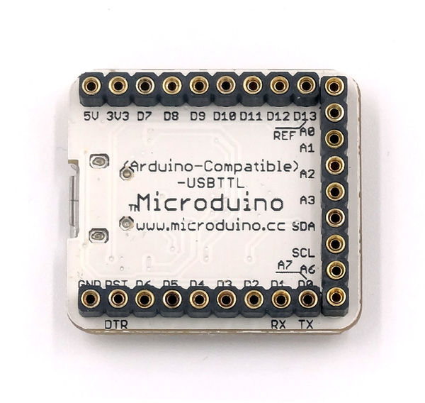
| − | [[file:Micromodule-FT232R- | + | [[file:Micromodule-FT232R-b.jpg|thumb|600px|center|Micromodule FT232R Back]] |
|} | |} | ||
2014年3月3日 (一) 04:30的最新版本
| Language | English |
|---|
|
Microduino-FT232R is a USB to serial UART interface module, it is based on FDTI FT232RL chip (Arduino embedded driver). Microduino-FT232R can be stacked with Microduino-Core or Microduino-Core+, enable Microduino core modules communicating with PC. The FT232R has optional clock generator output, and the new FTDIChip-ID? security dongle feature. In addition, asynchronous and synchronous bit bang interface modes are available. USB to serial designs using the FT232R is simplified by fully integrating the external EEPROM, clock circuit and USB resistors onto the device. |
Features
|
Specifications
|
Documents
|
DevelopmentUploading Arduino program to Microduino-Core/Core+ with Microduino-FT232R
|
Applications |
Buy |
History
|
Pictures |


