“开源LED点阵时钟/zh”的版本间的差异
(Created page with "{{Language|Microduino Lattice clock}} {| style="width: 800px;" |- | ==概述== *项目名称:Microduino 双色点阵级联 *目的:通过四个Microduino DcolorMatrix级...") |
|||
| (未显示4个用户的233个中间版本) | |||
| 第1行: | 第1行: | ||
{{Language|Microduino Lattice clock}} | {{Language|Microduino Lattice clock}} | ||
| − | {| style="width: | + | {| style="width: 1000px;" |
|- | |- | ||
| | | | ||
==概述== | ==概述== | ||
| − | *项目名称:Microduino | + | *项目名称:Microduino 点阵级联时钟 |
| − | * | + | *目的:实时显示时钟和字符。 |
| − | * | + | *难度:中级 |
| − | * | + | *耗时:2小时 |
| − | * | + | *制作者:peng |
| + | *简介 | ||
| + | **将四个[[Microduino-Module Dot Matrix/zh]]模块级联 | ||
| + | **使用蓝牙模块,通过手机APP校准点阵显示的时间 | ||
| + | **还可通过APP发送任意字符给点阵模块显示 | ||
==材料清单== | ==材料清单== | ||
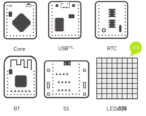
| − | + | {| border="0" cellpadding="10" width="100%" | |
| + | |- | ||
| + | |width="50%" valign="top" align="left"| | ||
| + | ===模块清单 === | ||
{|class="wikitable" | {|class="wikitable" | ||
|- | |- | ||
| 第23行: | 第30行: | ||
|[[Microduino-RTC/zh]]||1||读取时间 | |[[Microduino-RTC/zh]]||1||读取时间 | ||
|- | |- | ||
| − | |[[Microduino- | + | |[[Microduino-Module BLE/zh]]||1||手机与Core通讯 |
| + | |- | ||
| + | |[[Sensor-Dot Matrix-Color/zh]]||4||显示 | ||
| + | |- | ||
| + | |[[Microduino-Cube-S1/zh]]||1||扩展 | ||
|} | |} | ||
| − | + | |width="50%" valign="top" align="left"| | |
| + | |||
| + | ===其他材料=== | ||
{|class="wikitable" | {|class="wikitable" | ||
|- | |- | ||
| − | || | + | |部件||数量||功能 |
| + | |- | ||
| + | |USB数据线 || 1 ||供电,下载 | ||
| + | |- | ||
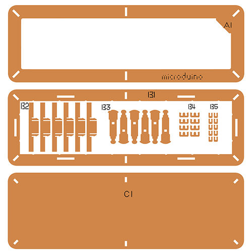
| + | |LED点阵时钟外壳套件 || 1 ||外壳 | ||
|- | |- | ||
| − | | | + | |双面胶 || 8 ||粘外壳 |
|- | |- | ||
| − | | | + | |尼龙螺丝 || 4 ||固定外壳 |
| + | |} | ||
|} | |} | ||
| + | {| border="0" cellpadding="10" width="100%" | ||
| + | |- | ||
| + | |width="50%" valign="top" align="left"| | ||
| + | [[File:matrixBOM1.jpg||500px|center]] | ||
| − | == | + | |width="50%" valign="top" align="left"| |
| − | + | [[File:matrixBOM2.jpg||500px|center]] | |
| − | |||
| − | + | |} | |
| − | |||
| + | ==实验原理== | ||
| − | + | *[[Sensor-Dot Matrix-Color/zh]]模块特点: | |
| + | **模块为8x8点阵,尺寸60mm*60mm; | ||
| + | **每个点颜色显示质量为24位,整体32k彩色显示效果 | ||
| + | **支持IIC通讯协议,IIC地址可设(1~64),点阵序列采用平面直角坐标系,便于控制 | ||
| − | + | *采用[[Microduino-Module BLE/zh]]蓝牙模块与手机通讯: | |
| + | **手机APP将字符串通过蓝牙模块发送给核心模块,并显示在点阵模块上。 | ||
| − | + | ==程序下载== | |
| + | *请保持更新下载Microduino官方最新的IDE | ||
| + | *从下面链接下载程序:[https://github.com/Microduino/Dot_Maxtrix_Clock Dot-Matrix-Clock.ino] | ||
| − | + | ==程序烧写== | |
| + | *将[[Microduino-Core/zh]]、[[Microduino-USBTTL/zh]]堆叠在一起。 | ||
| + | **用数据线连接其中的[[Microduino-USBTTL/zh]]准备上传程序。 | ||
| + | **注意:最好不要将所有模块堆叠在一起之后再上传程序 | ||
| + | *打开Arduino IDE for Microduino,环境,(搭建参考:[[AVR核心:Getting started/zh]]) | ||
| + | *点击【工具】,确认板卡(Microduino-Core),处理器(Atmega328P@16M,5V)选择无误,并选中对应端口号(COMX) | ||
| + | *点击【文件】->【打开】,浏览到项目程序地址,点击“Dot-Matrix-Clock.ino”程序打开 | ||
| + | *几项都无误后,点击"→"按钮下载程序到开发板上 | ||
| − | == | + | ==拼装过程== |
| − | + | {| border="0" cellpadding="10" width="100%" | |
| − | * | + | |- |
| − | + | |width="50%" valign="top" align="left"| | |
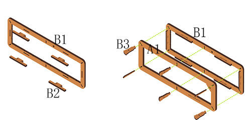
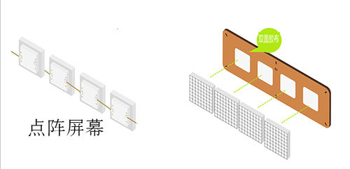
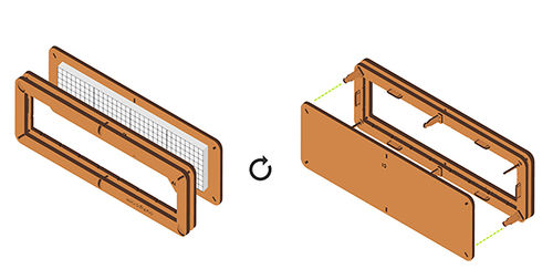
| + | *Step1: | ||
| + | **将结构B2垂直插入结构B1 | ||
| + | **利用结构B3将结构A1和结构B1连接 | ||
| + | |width="50%" valign="top" align="left"| | ||
| + | [[File:DotMatrixjiegou1.jpg|500px|center|thumb]] | ||
| + | |} | ||
| − | + | {| border="0" cellpadding="10" width="100%" | |
| − | + | |- | |
| − | + | |width="50%" valign="top" align="left"| | |
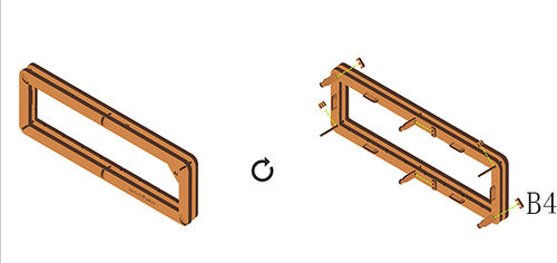
| + | *Step2: | ||
| + | **用结构B4卡住结构A1和结构B1 | ||
| + | |width="50%" valign="top" align="left"| | ||
| + | [[File:DotMatrixjiegou3.jpg|500px|center|thumb]] | ||
| + | |} | ||
| − | |||
| − | |||
| − | * | + | {| border="0" cellpadding="10" width="100%" |
| + | |- | ||
| + | |width="50%" valign="top" align="left"| | ||
| + | *Step3: | ||
| + | **更改点阵模块IIC地址可以参考[[https://www.microduino.cn/wiki/index.php/Microduino-Module_Dot_Matrix/zh#.E7.82.B9.E9.98.B5.E5.9C.B0.E5.9D.80.E8.AE.BE.E7.BD.AE.E6.96.B9.E6.B3.95 点阵模块IIC地址设置方法]]教程 | ||
| + | **将更改好IIC地址的点阵模块按定义的地址顺序从左往右连接,完成级连 | ||
| + | **将结构C1背面等距贴四个双面胶,把[[Sensor-Dot Matrix-Color/zh]]模块,依次粘在结构C1上(点阵有字母那边朝下) | ||
| + | **如下图所示,预留模块按键端接口的连线,以便于连接[[Microduino-Cube-S1/zh]]的IIC接口 | ||
| + | |width="50%" valign="top" align="left"| | ||
| + | [[File:DotMatrix1jilian.jpg|500px|center|thumb]] | ||
| + | |} | ||
| − | |||
| − | |||
| − | * | + | {| border="0" cellpadding="10" width="100%" |
| − | + | |- | |
| − | [[File: | + | |width="50%" valign="top" align="left"| |
| − | * | + | *Step4: |
| + | **用结构B3将结构C1和结构A1,B1连接 | ||
| + | |width="50%" valign="top" align="left"| | ||
| + | [[File:DotMatrixjiegou4.jpg|500px|center|thumb]] | ||
| + | |} | ||
| + | |||
| + | |||
| + | {| border="0" cellpadding="10" width="100%" | ||
| + | |- | ||
| + | |width="50%" valign="top" align="left"| | ||
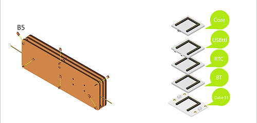
| + | *Step5: | ||
| + | **用结构B5卡住结构B3 | ||
| + | **将以下模块叠在[[Microduino-Cube-S1/zh]]上 | ||
| + | ***[[Microduino-Core/zh]] | ||
| + | ***[[Microduino-USBTTL/zh]] | ||
| + | ***[[Microduino-RTC/zh]] | ||
| + | ***[[Microduino-BT/zh]] | ||
| + | |width="50%" valign="top" align="left"| | ||
| + | [[File:DotMatrixjiegou7.jpg|500px|center|thumb]] | ||
| + | |} | ||
| + | |||
| + | {| border="0" cellpadding="10" width="100%" | ||
| + | |- | ||
| + | |width="50%" valign="top" align="left"| | ||
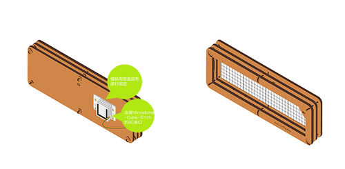
| + | *Step6: | ||
| + | **把[[Sensor-Dot Matrix-Color/zh]]模块连接[[Microduino-Cube-S1/zh]]的IIC接口 | ||
| + | **用尼龙螺丝把[[Microduino-Cube-S1/zh]]固定在结构C1背面 | ||
| + | |width="50%" valign="top" align="left"| | ||
| + | [[File:DotMatrixjiegou5.jpg|500px|center|thumb]] | ||
| + | |} | ||
| − | + | ==操作说明== | |
| − | + | *APP文件下载[[File:blueclock.zip]] | |
| + | ===蓝牙连接=== | ||
| + | {| border="0" cellpadding="10" width="100%" | ||
| + | |- | ||
| + | |width="50%" valign="top" align="left"| | ||
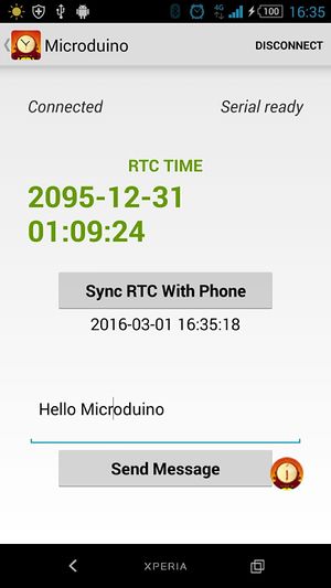
| + | *确定手机蓝牙已打开,使用APP搜索名为“Microduino”的蓝牙设备 | ||
| + | *连接成功,即可进行控制 | ||
| + | ===校准时间=== | ||
| + | |||
| + | *鉴于RTC模块长时间不供电会造成时间丢失的现象,我们添加了通过蓝牙模块,利用APP校正时间 | ||
| + | **点击“sync time with phone”按钮即可校正点阵的时间 | ||
| + | |width="50%" valign="top" align="left"| | ||
| + | [[File:DcolorMatrix ble.jpg|300px|center|thumb]] | ||
| + | |||
| + | |} | ||
| + | |||
| + | ===显示文字=== | ||
| + | {| border="0" cellpadding="10" width="100%" | ||
| + | |- | ||
| + | |width="50%" valign="top" align="left"| | ||
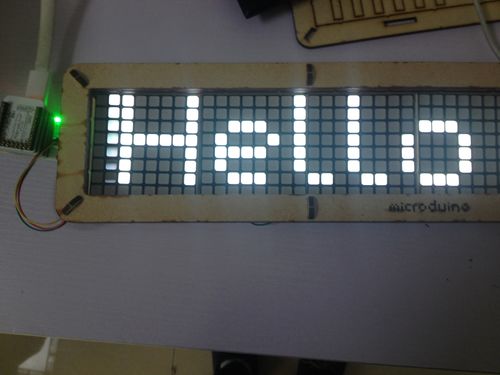
| + | *在输入栏写入‘hello microduino’,点击“send message”,点阵屏幕上会显示输入的字符 | ||
| + | |width="50%" valign="top" align="left"| | ||
| + | [[File:DotMatrixBle.jpg|500px|center|thumb]] | ||
| + | |} | ||
| − | + | ==代码说明== | |
| + | 代码下载:[[File:Dot Maxtrix Clock.zip]] | ||
| + | ===点阵级联=== | ||
| + | uint8_t Addr[MatrixPix_X][MatrixPix_Y] = { | ||
| + | { 64, 63, 62, 61}}; | ||
| + | 定义了四个Dot Matrix模块的IIC地址是64,63,62,61,排列方式是1x4。 | ||
| − | + | ===蓝牙=== | |
| − | |||
| − | |||
| − | |||
| − | |||
| − | |||
| − | |||
| − | |||
| − | |||
| − | |||
| − | |||
| − | |||
| − | |||
| − | |||
| − | |||
| − | |||
| − | |||
| − | |||
| − | |||
| − | |||
| − | |||
| − | |||
| − | |||
| − | |||
| − | |||
| − | |||
| − | |||
| − | |||
| − | == | + | while (mySerial.available()) {...} |
| − | + | 当串口有数据时有效。 | |
| + | mySerial.read() | ||
| + | 读取软串口传输的数据 | ||
| + | if (c == 't' && buffer_num == 0 && !buffer_sta_d) | ||
| + | buffer_sta_t = true; | ||
| + | if (c == 'm' && buffer_num == 0 && !buffer_sta_t) | ||
| + | buffer_sta_d = true; | ||
| + | 判断是日期数据还是时间数据 | ||
| + | strstr((char *)buffer, "t") | ||
| + | 返回buffer中第一次出现"t"字符的地址 | ||
| + | sscanf((char *)strstr((char *)buffer, "t"), "t%d,%d,%d,%d,%d,%d", &sta[0], &sta[1], &sta[2], &sta[3], &sta[4], &sta[5]); | ||
| + | 从buffer中"t"字符第一次出现的地址起,按%d格式读取数值写入到sta[]中 | ||
| + | bleUpdata() | ||
| + | 通过软串口传输数据,手机上按钮只有在按下 情况下发送指定字符,如果松开就就发送“0”字符,这样在没有按下情况下,将会一直显示时间。 | ||
| − | == | + | ===RTC=== |
| − | |||
| − | == | ||
| − | |||
| − | + | rtc.getDate(); | |
| + | rtc.getTime(); | ||
| + | setTime(rtc.getHour(), rtc.getMinute(), rtc.getSecond(), rtc.getDay(), rtc.getMonth(), rtc.getYear()) | ||
| + | 获得rtc的日期时间数据 | ||
| + | rtc.setDate(day(), weekday() , month(), 0, year() - 2000); //day, weekday, month, century(1=1900, 0=2000), year(0-99) | ||
| + | rtc.setTime(hour(), minute() , second()); //hr, min, sec | ||
| + | 按时,分,秒,日,月,年设置 | ||
| − | + | ===display=== | |
| − | |||
| − | |||
| − | + | display.print(second() % 2 ? " " : ":"); | |
| + | 闪速的秒钟,用过判断秒是否能被2整除,如果能就显示,否者不显示 | ||
| + | display.getDeviceAddr(a) | ||
| + | 获得设备IIC地址 | ||
| + | display.getWidth(),display.getHeight() | ||
| + | 返回X,Y坐标 | ||
| + | display.setLedColor(x, y, random(0, 255), random(0, 255), random(0, 255)) | ||
| + | 随机设置每个LED的颜色 | ||
| + | display.clearDisplay() | ||
| + | 清理屏幕显示 | ||
| + | display.setColor(X,Y,Z) | ||
| + | 设置全屏颜色 X:红色 Y:绿色 Z:蓝色 | ||
| + | display.writeString("string", MODE, time ,z) | ||
| + | string:任意字符串, MODE:MODE_H横向显示字符/MODE_V竖向显示字符, time:显示的时间(字符在屏幕流动速度) ,z:X/Y坐标 | ||
| − | + | 通过读取RTC时钟,将特定的数值以坐标形式显示出来就行。 | |
| − | |||
| − | |||
| − | |||
| − | |||
| − | |||
| + | ==疑难解答/FAQ== | ||
| + | *Q:怎么知道[[Sensor-Dot Matrix-Color/zh]]模块IIC地址是多少? | ||
| + | **A:查阅[[https://www.microduino.cn/wiki/index.php/Microduino-Module_Dot_Matrix/zh#.E7.82.B9.E9.98.B5.E5.9C.B0.E5.9D.80.E8.AE.BE.E7.BD.AE.E6.96.B9.E6.B3.95 点阵模块IIC地址设置方法]]教程 | ||
| + | *Q:多个点阵模块按什么顺序连接? | ||
| + | **A:按[[Sensor-Dot Matrix-Color/zh]]模块设置的IIC地址顺序从左往右连接 | ||
| + | *Q:怎么知道手机有没有连接到蓝牙模块? | ||
| + | **A:APP界面左上角显示connected即连接成功 | ||
| + | *Q:蓝牙模块的跳线是什么意思? | ||
| + | **A:本教程中蓝牙模块采用的是默认软串口mySerial(4,5),不需要跳线。深入了解蓝牙模块可参考蓝模块配置[https://www.microduino.cn/wiki/index.php/Microduino-Module_BLE/zh#.E5.BC.95.E8.84.9A.E8.AF.B4.E6.98.8E Microduino-Module BLE引脚说明]。 | ||
|} | |} | ||
| + | [[开源LED点阵时钟|返回新开源LED点阵时钟]] | ||
2017年8月2日 (三) 10:14的最新版本
| Language | English |
|---|
目录概述
材料清单
实验原理
程序下载
程序烧写
拼装过程
操作说明
蓝牙连接
显示文字
代码说明点阵级联 uint8_t Addr[MatrixPix_X][MatrixPix_Y] = {
{ 64, 63, 62, 61}};
定义了四个Dot Matrix模块的IIC地址是64,63,62,61,排列方式是1x4。 蓝牙 while (mySerial.available()) {...}
当串口有数据时有效。 mySerial.read() 读取软串口传输的数据 if (c == 't' && buffer_num == 0 && !buffer_sta_d)
buffer_sta_t = true;
if (c == 'm' && buffer_num == 0 && !buffer_sta_t)
buffer_sta_d = true;
判断是日期数据还是时间数据 strstr((char *)buffer, "t") 返回buffer中第一次出现"t"字符的地址 sscanf((char *)strstr((char *)buffer, "t"), "t%d,%d,%d,%d,%d,%d", &sta[0], &sta[1], &sta[2], &sta[3], &sta[4], &sta[5]); 从buffer中"t"字符第一次出现的地址起,按%d格式读取数值写入到sta[]中 bleUpdata() 通过软串口传输数据,手机上按钮只有在按下 情况下发送指定字符,如果松开就就发送“0”字符,这样在没有按下情况下,将会一直显示时间。 RTCrtc.getDate(); rtc.getTime(); setTime(rtc.getHour(), rtc.getMinute(), rtc.getSecond(), rtc.getDay(), rtc.getMonth(), rtc.getYear()) 获得rtc的日期时间数据 rtc.setDate(day(), weekday() , month(), 0, year() - 2000); //day, weekday, month, century(1=1900, 0=2000), year(0-99) rtc.setTime(hour(), minute() , second()); //hr, min, sec 按时,分,秒,日,月,年设置 displaydisplay.print(second() % 2 ? " " : ":"); 闪速的秒钟,用过判断秒是否能被2整除,如果能就显示,否者不显示 display.getDeviceAddr(a) 获得设备IIC地址 display.getWidth(),display.getHeight() 返回X,Y坐标 display.setLedColor(x, y, random(0, 255), random(0, 255), random(0, 255)) 随机设置每个LED的颜色 display.clearDisplay() 清理屏幕显示 display.setColor(X,Y,Z) 设置全屏颜色 X:红色 Y:绿色 Z:蓝色 display.writeString("string", MODE, time ,z)
string:任意字符串, MODE:MODE_H横向显示字符/MODE_V竖向显示字符, time:显示的时间(字符在屏幕流动速度) ,z:X/Y坐标 通过读取RTC时钟,将特定的数值以坐标形式显示出来就行。 疑难解答/FAQ
|
