“Lesson 8--Microduino "Pulse Recorder"”的版本间的差异
(→Experiment Schematic) |
|||
| (未显示3个用户的10个中间版本) | |||
| 第4行: | 第4行: | ||
| | | | ||
==Objective== | ==Objective== | ||
| − | + | In lesson 3, you learned how to use a button and avoid the issue of electrical noise. The solution was to add a short delay. | |
| − | + | However, this solution has a disadvantage. Different people will take different amounts of time to press a button. That means the delay must be different for different people, too. | |
| − | This lesson will | + | This lesson will teach you how to get the duration that a button is pressed down. This program uses pulse timing calculation. |
| − | + | In addition, you will learn about Arduino's serial port to monitor the data. | |
==Equipment== | ==Equipment== | ||
| 第13行: | 第13行: | ||
*'''[[Microduino-FT232R]]''' | *'''[[Microduino-FT232R]]''' | ||
*Other hardware equipment | *Other hardware equipment | ||
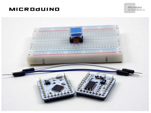
| − | **Breadboard | + | **1x Box of breadboard jumper wires |
| − | ** | + | **1x Breadboard |
| − | **Button | + | **1x Ceramic capacitor |
| − | **USB Data cable | + | **1x Button |
| + | **1x USB Data cable | ||
| + | |||
| + | [[File:lesson8All.jpg|600px|center|thumb]] | ||
==Pulse== | ==Pulse== | ||
| − | Pulse is a | + | Pulse is a rapid, transient change in the amplitude of a signal from a baseline value to a higher or lower value, followed by a rapid return to the baseline value. |
| − | In Microduino, pulse | + | In Microduino, pulse is simply a digital signal which changes between high and low in a cyclical pattern. Pulse timing is often used to calculate the speed in electronic components. |
| − | Pulse timing is often used | ||
| − | == | + | ==Experiment Schematic== |
[[File:lesson8-schematic.jpg|600px|center|thumb]] | [[File:lesson8-schematic.jpg|600px|center|thumb]] | ||
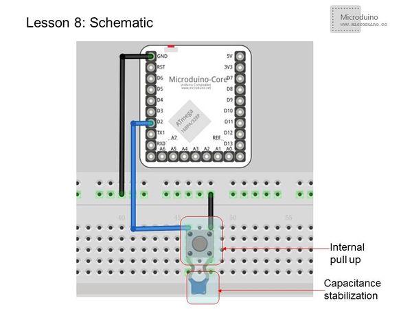
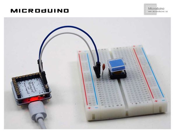
| − | + | This schematic uses the internal pull-up. We also connected an external ceramic capacitor for stabilization. | |
==Program== | ==Program== | ||
| 第41行: | 第43行: | ||
{ | { | ||
//Read low pulse from the pin, the maximum pulse interval is 60 seconds, and assign the result to the variable time1 | //Read low pulse from the pin, the maximum pulse interval is 60 seconds, and assign the result to the variable time1 | ||
| − | time1= pulseIn(pin, LOW,60000000)/1000;//Convert the time to ms | + | time1= pulseIn(pin, LOW, 60000000)/1000; //Convert the time to ms |
| − | Serial.print(time1); //Output the time1 by serial | + | Serial.print(time1); //Output the time1 by serial |
Serial.print("ms "); | Serial.print("ms "); | ||
| − | time2= pulseIn(pin, LOW,60000000)/1000.0;//Convert the time to ms | + | time2= pulseIn(pin, LOW,60000000)/1000.0; //Convert the time to ms |
| − | Serial.print(time2); //Output | + | Serial.print(time2); //Output time1 by serial |
| − | Serial.println("ms");// | + | Serial.println("ms"); //Output time2 by serial and start a new line |
| − | |||
} | } | ||
| + | |||
</source> | </source> | ||
| − | ==Serial | + | ==Serial Monitoring== |
===Open the serial port monitor=== | ===Open the serial port monitor=== | ||
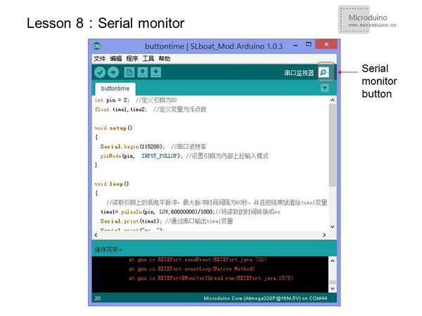
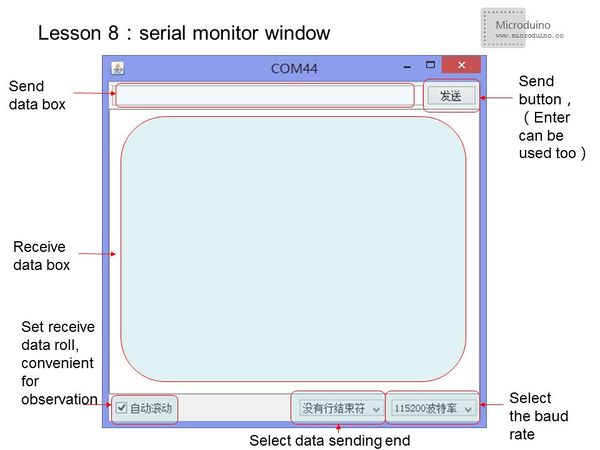
| − | *Click the Serial Monitor button | + | *Click the Serial Monitor button to pop-up the serial monitor interface. |
[[File:lesson8-serialmonitor.jpg|600px|center|thumb]] | [[File:lesson8-serialmonitor.jpg|600px|center|thumb]] | ||
[[File:lesson8-serialwindow.jpg|600px|center|thumb]] | [[File:lesson8-serialwindow.jpg|600px|center|thumb]] | ||
*Note: | *Note: | ||
| − | **In order to | + | **In order to use serial, you must add the line "Serial.begin(xxxx)" in function setup(),xxxx is the baud rate. The baud rate is the rate at which data is transferred to your computer from the [[Microduino-Core]]. The units is bits per second. |
| − | ** | + | **It is important that the baud rate should be set to the same number when using the serial monitor. If they do not match up, you will only see gibberish on your serial monitor. |
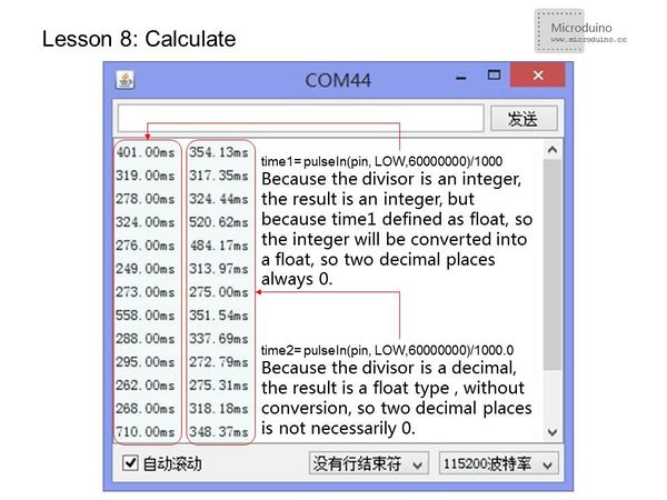
| − | *When | + | *When converting units (as in the case of microseconds to milliseconds), you need to pay attention to the data types: |
[[File:lesson-calculate.jpg|600px|center|thumb]] | [[File:lesson-calculate.jpg|600px|center|thumb]] | ||
| − | === | + | ===pulseIn() usage=== |
| − | * | + | *Function:Reads a pulse (either HIGH or LOW) on a pin. For example, if value is HIGH, pulseIn() waits for the pin to go HIGH, starts timing, then waits for the pin to go LOW and stops timing. Returns the length of the pulse in microseconds. Gives up and returns 0 if no pulse starts within a specified time out. This function is accurate for pulse ranges of 10microseconds ~ 3mins. (1s=1,000 milliseconds=1,000,000 microseconds) |
| − | + | *Syntax: | |
| − | * | ||
**pulseIn(pin, value) | **pulseIn(pin, value) | ||
**pulseIn(pin, value, timeout) | **pulseIn(pin, value, timeout) | ||
*Parameters: | *Parameters: | ||
| − | **pin: pulse | + | **pin: the number of the pin on which you want to read the pulse. (int) |
| − | **value:pulse | + | **value: type of pulse to read: either HIGH or LOW. (int) |
| − | **timeout (optional) | + | **timeout (optional):the number of microseconds to wait for the pulse to start; default is one second (unsigned long) |
==Result== | ==Result== | ||
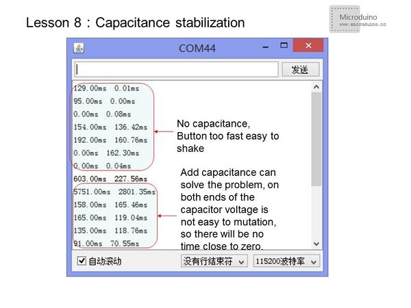
| − | For | + | For stabilization, add a ceramic capacitor in the signal change port. You will be able to see better results. |
[[File:lesson8-capacitance.jpg|600px|center|thumb]] | [[File:lesson8-capacitance.jpg|600px|center|thumb]] | ||
| + | [[File:lesson8Result.jpg|600px|center|thumb]] | ||
| + | |||
==Video== | ==Video== | ||
| + | https://www.youtube.com/watch?v=Ge52Sx_8XeU | ||
|} | |} | ||
2015年7月15日 (三) 00:11的最新版本
| Language | English |
|---|
目录ObjectiveIn lesson 3, you learned how to use a button and avoid the issue of electrical noise. The solution was to add a short delay. However, this solution has a disadvantage. Different people will take different amounts of time to press a button. That means the delay must be different for different people, too. This lesson will teach you how to get the duration that a button is pressed down. This program uses pulse timing calculation. In addition, you will learn about Arduino's serial port to monitor the data. Equipment
PulsePulse is a rapid, transient change in the amplitude of a signal from a baseline value to a higher or lower value, followed by a rapid return to the baseline value. In Microduino, pulse is simply a digital signal which changes between high and low in a cyclical pattern. Pulse timing is often used to calculate the speed in electronic components. Experiment SchematicThis schematic uses the internal pull-up. We also connected an external ceramic capacitor for stabilization. Programint pin = 2; //Define Pin D2
float time1,time2; //Define variables to float
void setup()
{
Serial.begin(115200); //Serial port baud rate
pinMode(pin, INPUT_PULLUP); //Set pin to input mode with the internal pull-up
}
void loop()
{
//Read low pulse from the pin, the maximum pulse interval is 60 seconds, and assign the result to the variable time1
time1= pulseIn(pin, LOW, 60000000)/1000; //Convert the time to ms
Serial.print(time1); //Output the time1 by serial
Serial.print("ms ");
time2= pulseIn(pin, LOW,60000000)/1000.0; //Convert the time to ms
Serial.print(time2); //Output time1 by serial
Serial.println("ms"); //Output time2 by serial and start a new line
}
Serial MonitoringOpen the serial port monitor
pulseIn() usage
ResultFor stabilization, add a ceramic capacitor in the signal change port. You will be able to see better results. Video |
