|
|
| (未显示5个用户的79个中间版本) |
| 第2行: |
第2行: |
| | {| style="width: 800px;" | | {| style="width: 800px;" |
| | | | | | |
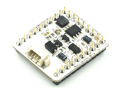
| − | [[File:Microduino-BM-rect.jpg|400px|thumb|right|Microduino-BM]] | + | [[File:Microduino-bm-new.jpg|400px|thumb|right|Microduino-BM]] |
| − | | |
| − | | |
| − | Microduino-BM是一款集成了单节锂电池充电管理、电量检测及LED指示、升压到5V输出、LDO到3.3V输出的放电管理模块。
| |
| − | | |
| − | | |
| − | | |
| − | | |
| − | | |
| | | | |
| | | | |
| | + | Microduino-BM_Li-ion是一款单节锂电池升压到5V输出、LDO到3.3V输出的放电管理模块。需要配合[[Microduino Module BM Shield/zh]]来使用。 |
| | | | |
| | + | 原模块参考[[Microduino-Module_BM_Li-ion(old)/zh]]。 |
| | | | |
| | | | |
| | ==特色== | | ==特色== |
| − | *充放电管理、电量检测、5v升压、3.3v LDO高度集成; | + | *支持UPS(需配合[[Microduino Module BM Shield/zh]]); |
| − | *拨档开关切换充放电、一键开启、休眠模块;
| + | *电量检测、5v升压、3.3v LDO高度集成; |
| | *小巧、便宜、堆叠、开放; | | *小巧、便宜、堆叠、开放; |
| | *统一的 Microduino 接口规范,和丰富的外围模块,可方便、灵活的与其他符合 Microduino 接口规范的模块、传感器进行快速的连接和扩展; | | *统一的 Microduino 接口规范,和丰富的外围模块,可方便、灵活的与其他符合 Microduino 接口规范的模块、传感器进行快速的连接和扩展; |
| 第25行: |
第19行: |
| | ==规格== | | ==规格== |
| | *首先来看看本模块的接口: | | *首先来看看本模块的接口: |
| − | **一个按键开关 | + | **一个1.27间距的4Pin接口("VUSB","SWI","BAT"以及"GND"); |
| − | **一个两档拨档开关
| + | **UPIN27上起作用的接口有5V、3V3、GND;BM上的模拟电压检测可以在A6和A7之间进行选择,可以利用mcu检测电池的电压来判断电池的电量,不要依靠保护电路保护电池,保护电路只是极端情况下才起作用。 |
| − | **一个双2.54电池接口(“+”接电池正极,“-”接电池负极)
| |
| − | **UPIN27上起作用的接口有5V、3V3、GND: | |
| | | | |
| − | ===充电===
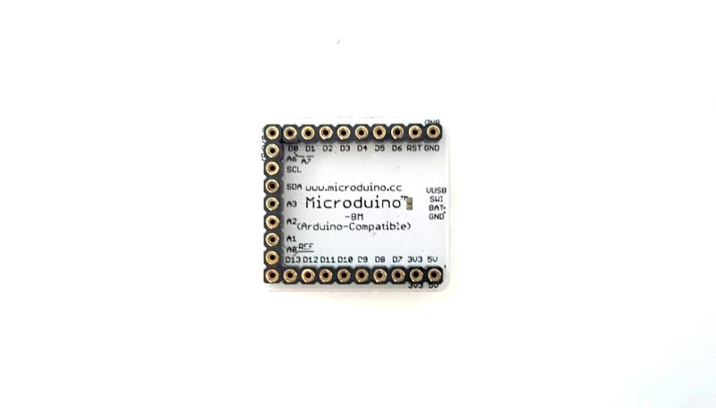
| + | '''引脚说明''' |
| − | *先接入外置5V充电电源,再将开关切换到“IN”,模块进入充电状态,此时4个LED指示灯做浪涌式充电指示(详细显示模式请参考HT4901文档),最大充电流为500mA,充电完成*后先将开关置于OUT,再拔下外置5V充电电源。
| |
| − | *注意事项:
| |
| − | **充电过程务必遵循以下过程:确定开关置于OUT、插上电池、接入外置5V充电电源、将开关置于IN、开始充电、充电完毕、将开关置于OUT、拔下外置5V充电电源。
| |
| − | **充电电源推荐:电压5v,电流600ma以上;
| |
| − | **不得添加对压降有影响的元件(如二极管)在充电回路中,以免达不到充电电压进而影响充电电流。
| |
| | | | |
| − | ===放电===
| + | [[file:Microduino-bm-new.jpg|800px|thumb|center|pinout]] |
| − | *请先确认开关置于OUT,接入电池后,在待机状态时,短按按键开关(时间>50mS),模块即从待机状态唤醒;此时启动升压输出,同时开启UPIN27的GND回路:5V接口输出5V电压,最大电流500mA;同时3V3接口输出3.3V电压,最大电流250mA。
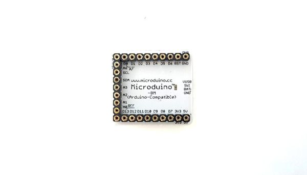
| + | [[file:Microduino-bm-new-2.jpg|800px|thumb|center|pinout]] |
| − | *在电池电压欠压(3.3V)或进入限流/短路保护时关闭升压输出,进入待机模式。
| |
| − | *注意事项:
| |
| − | **请先确认开关置于OUT再启动升压输出;
| |
| − | **电池供电过程中请不要拨动开关。
| |
| | | | |
| − | ===电量检测=== | + | ===供电=== |
| − | *请先确认开关置于OUT,接入电池后,短按按键开关,对内置电池电量检测;并通过4个LED指示灯作电量显示,电量显示3~5S后关闭。 | + | *当接上Microduino Module BM Shield时且处于供电状态,5v提供1a的电力输出,3.3v提供700ma的电力输出。 |
| − | | |
| − | ===待机===
| |
| − | *(待机就是断开UPIN27的GND回路,且BM整体功耗可控制在30uA之内)
| |
| − | *请先确认开关置于OUT,接入电池后若不进行任何操作,此时默认是待机模式。
| |
| − | *当你已经开启放电模式时,可通过长按按键开关(3s以上)来进入待机模式。
| |
| − | *智能检测:没有充电输入、没有放电输出(<10mA)3分钟内进入待机模式。
| |
| | | | |
| | ==文档== | | ==文档== |
| − | Eagle PCB '''[[File:Microduino-BM.zip]]'''
| + | PCB ''[[File:Battery Mange.rar]]'' |
| | | | |
| | ===主要元件=== | | ===主要元件=== |
| − | *芯片1:HT4901 HT4901应用指导 '''[[Media: HT4901 Application guidelines V1.1.pdf]] | + | *MOS管:AO3407 '''[[File:AO3407.pdf]]''' |
| − | *芯片2:LP2985AIM5X-3.3 '''[[File:LP2985.pdf]]'''
| |
| − | *MOS管:AO3400 '''[[File:AO3400.pdf]]'''
| |
| − | *肖特基二极管:MBR0520 '''[[File:MBR0520.pdf]]'''
| |
| − | *拨动开关:MSK-12C01(1P2T) '''[[File:MSK-12C01(1P2T).pdf]]'''
| |
| | | | |
| | ==开发== | | ==开发== |
| − | *电池:单节3.7v锂电池; | + | *Microduino Module BM Shield,并接上3.7单节锂电池或接上USB; |
| − | *建议电池与模块以2PIN杜邦相连; | + | *用1.27间距的4PIN线连接Microduino Module BM Shield; |
| − | *建议电源选择:电压5V,电流600ma以上,如:电脑USB、5V手机充电器。 | + | *电量计算: |
| | + | <source lang="cpp"> |
| | | | |
| − | ==应用==
| + | //电压检测引脚,BM Shield默认是A7引脚 |
| − | When viewing the board with the battery connector and switches closest to you, with the component side up, the battery connector positive (+) pin is on the left and the ground (-) pin is on the right. The pushbutton switch is on the left and the mode switch (IN = Charge, lever to the left; OUT = Discharge, lever to the right) is on the right.
| + | #define PIN_bat A7 //BAT |
| | | | |
| − | After connecting the battery you must momentarily push the pushbutton switch to start the converter. You can stop the converter/turn off the power by unplugging the battery or by pressing and holding the pushbutton for a few seconds. To use the battery to generate +5 VDC and +3.3 VDC, set the mode switch (to the right of the battery connector when viewed as described above) to OUT (switch lever away from the battery connector). The IN position is used for charging the battery from an external 5VDC, >=600 mA source.
| + | //MCU工作电压,需要根据情况选择 |
| | + | #define MCU_VOLTAGE 50 |
| | + | //#define MCU_VOLTAGE 33 |
| | | | |
| − | The charging current is 500 mA, so I recommend a battery with at least 500 mAH of capacity to avoid charging at a rate >1C.
| + | #define _V_max 41 //4.2V |
| | + | #define _V_min 35 //3.7V |
| | | | |
| − | A rough English translation of the charging process is as follows:
| + | #define _V_fix 0.2 //fix battery voltage |
| | + | #define _V_math(Y) (_V_fix+((Y*analogRead(PIN_bat)/1023.0f)/(33.0f/(51.0f+33.0f)))) |
| | | | |
| − | *Set the mode switch to OUT (switch lever away from the battery connector);
| + | uint8_t batVoltage() { |
| − | *Plug in the battery;
| + | return constrain(_V_math(MCU_VOLTAGE), _V_min, _V_max); |
| − | *Plug in the external 5VDC power supply (at least a 600 mA supply recommended);
| + | } |
| − | *Set the mode switch to IN (switch lever toward the battery connector);
| |
| − | *When charging is complete as indicated by all 4 LEDs on, set the mode switch to OUT (switch lever away from the battery connector);
| |
| − | *Unplug the external 5VDC power supply.
| |
| | | | |
| − | The LED indications seem to be as follows, based on how Google Translate translates the Chinese datasheet for the HOTCHIP HT4901 at http://www.hotchip.com.cn/DownFiles/20131126090806453.pdf:
| + | </source> |
| | | | |
| − | <u>Discharge Mode</u>
| + | ==应用== |
| − | :{|class="wikitable"
| + | *锂电池升压给Microduino核心供电 |
| − | |-
| |
| − | !Voltage
| |
| − | ! LED1
| |
| − | ! LED2
| |
| − | ! LED3
| |
| − | ! LED4
| |
| − | |-
| |
| − | |3.2-3.5V
| |
| − | | ON
| |
| − | | OFF
| |
| − | | OFF
| |
| − | | OFF
| |
| − | |-
| |
| − | |3.5-3.65V
| |
| − | | ON
| |
| − | | ON
| |
| − | | OFF
| |
| − | | OFF
| |
| − | |-
| |
| − | |3.65-3.95V
| |
| − | | ON
| |
| − | | ON
| |
| − | | ON
| |
| − | | OFF
| |
| − | |-
| |
| − | | > 3.95V
| |
| − | | ON
| |
| − | | ON
| |
| − | | ON
| |
| − | | ON
| |
| − | |-
| |
| − | |}
| |
| − | If the voltage drops below 3.2V, LED1 flashes and within 5 seconds the HT4901 goes to standby mode (I think... or should I say I hope...) to avoid over-discharging your battery.
| |
| − | | |
| − | <u>Charge Mode</u>
| |
| − | :{|class="wikitable"
| |
| − | |-
| |
| − | !Voltage
| |
| − | ! LED1
| |
| − | ! LED2
| |
| − | ! LED3
| |
| − | ! LED4
| |
| − | |-
| |
| − | | <3.4V
| |
| − | |FLASH
| |
| − | |FLASH
| |
| − | |FLASH
| |
| − | |FLASH
| |
| − | |-
| |
| − | |3.4-3.8V
| |
| − | | ON
| |
| − | |FLASH
| |
| − | |FLASH
| |
| − | |FLASH
| |
| − | |-
| |
| − | |3.8-4.0V
| |
| − | | ON
| |
| − | | ON
| |
| − | |FLASH
| |
| − | |FLASH
| |
| − | |-
| |
| − | |4.0-4.25V
| |
| − | | ON
| |
| − | | ON
| |
| − | | ON
| |
| − | |FLASH
| |
| − | |-
| |
| − | |-
| |
| − | |>= 4.25V
| |
| − | | ON
| |
| − | | ON
| |
| − | | ON
| |
| − | | ON
| |
| − | |}
| |
| − | Be prepared to terminate the charging process immediately when all four LEDs are on and steady. Overcharging lithium-type batteries may result in a nasty fire. I don't know how good the HT4901 is at detecting that the charging process is complete and shutting off the charging current to the battery.
| |
| − | | |
| − | Hope I correctly translated this information. /Chip
| |
| − | | |
| − | [[File:BM-Pinout-1.jpg|800px|thumb|center|Microduino-BM-Pinout1]]
| |
| − | [[File:BM-Pinout-2.jpg|800px|thumb|center|Microduino-BM-Pinout2]]
| |
| | | | |
| − | ==购买== | + | ==问题解答== |
| | | | |
| | ==历史== | | ==历史== |
| − | *2013年11月14日新版发布,主要改进: | + | *2016年,在原来模块基础上分离出Microduino Module BM Shield; |
| | + | *2014年7月29版发布,主要改进: |
| | + | **取消了拨动开关控制充放电,直接用mcirousb充电; |
| | + | **支持UPS。 |
| | + | *2013年11月14日新版发布,主要改进:https://www.microduino.cc/wiki/index.php?title=Microduino-BM/zh&oldid=1041 |
| | **取消了VMOT引脚,改用拨动开关直接利用5V口切换充放电; | | **取消了VMOT引脚,改用拨动开关直接利用5V口切换充放电; |
| | **升压按键可以完全控制升压、UPIN27的GND回路的通断。 | | **升压按键可以完全控制升压、UPIN27的GND回路的通断。 |
| 第184行: |
第83行: |
| | | | |
| | ==图库== | | ==图库== |
| − | [[file:Micrmodule-BM-t.jpg|thumb|600px|center|Micrmodule BM Front]] | + | [[file:Microduino-bm-new.jpg|thumb|600px|center|Micrmodule BM Front]] |
| − | [[file:Micrmodule-BM-b.jpg|thumb|600px|center|Micrmodule BM Back]] | + | [[file:Microduino-bm-new-2.jpg|thumb|600px|center|Micrmodule BM Back]] |
| | |} | | |} |


