“Microduino-Core+”的版本间的差异
(→Pictures) |
|||
| (未显示2个用户的2个中间版本) | |||
| 第102行: | 第102行: | ||
| 32 | | 32 | ||
| 8 | | 8 | ||
| − | | | + | | 8 |
| 2 | | 2 | ||
|- | |- | ||
| 第111行: | 第111行: | ||
| 32 | | 32 | ||
| 8 | | 8 | ||
| − | | | + | | 8 |
| 2 | | 2 | ||
|} | |} | ||
| 第136行: | 第136行: | ||
* Microcontroller: ATmega644PA/ATmega1284P | * Microcontroller: ATmega644PA/ATmega1284P | ||
* Operating Voltage: 5V/3.3V | * Operating Voltage: 5V/3.3V | ||
| − | * Digital I/O Pins: 24 (of which | + | * Digital I/O Pins: 24 (of which 8 provide PWM output with D7,D8,D9,D10,D12,D13,D22 and D23, PWM ports are different to '''[[Microduino-Core]]''') |
* Analog Input Pins: 8 (2 more comparing to Arduino Uno) | * Analog Input Pins: 8 (2 more comparing to Arduino Uno) | ||
* DC Current per I/O Pin: 40 mA | * DC Current per I/O Pin: 40 mA | ||
| 第142行: | 第142行: | ||
* Serial: 2 set of serial ports. D0 (RX0) + D1 (TX0) and D2 (RX1) + D3 (TX1), used to receive (RX) and transmit (TX) TTL serial data. | * Serial: 2 set of serial ports. D0 (RX0) + D1 (TX0) and D2 (RX1) + D3 (TX1), used to receive (RX) and transmit (TX) TTL serial data. | ||
* External Interrupts: 2, 3 and 6. These pins can be configured to trigger an interrupt on a low value, a rising or falling edge, or a change in value. See the attachInterrupt() function for details. | * External Interrupts: 2, 3 and 6. These pins can be configured to trigger an interrupt on a low value, a rising or falling edge, or a change in value. See the attachInterrupt() function for details. | ||
| − | * PWM: 7, 8, 9, 10, 22 and 23. Provide 8-bit PWM output with the analogWrite() function. | + | * PWM: 7, 8, 9, 10, 12, 13, 22 and 23. Provide 8-bit PWM output with the analogWrite() function. |
* SPI: 10 (SS), 11 (MOSI), 12 (MISO), 13 (SCK). These pins support SPI communication using the SPI library. | * SPI: 10 (SS), 11 (MOSI), 12 (MISO), 13 (SCK). These pins support SPI communication using the SPI library. | ||
* IIC: D20 (SDA) pin and D21 (SCL) pin. Support TWI communication using the Wire library. | * IIC: D20 (SDA) pin and D21 (SCL) pin. Support TWI communication using the Wire library. | ||
| 第229行: | 第229行: | ||
|- | |- | ||
| | | | ||
| + | |||
| + | ==FQA== | ||
| + | *Do you have ATmega1284P @ 8M 3.3V version? | ||
| + | **So far no. | ||
==Buy== | ==Buy== | ||
2014年10月8日 (三) 14:09的最新版本
| Language | English |
|---|
|
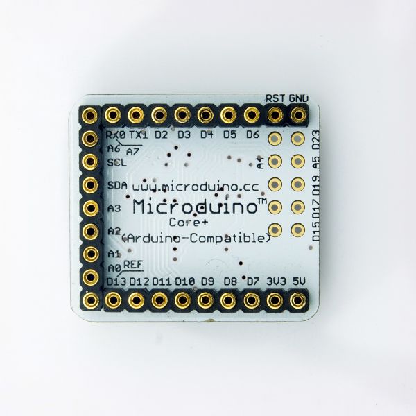
Microduino-Core+ is one of core modules of Microduino series, using Atmel ATmega644PA/ATmega1284P series as main chip, it is a performance enhanced version of Microduino-Core. Microduino-Core+ has all features of –Core, can be stacked with modules through UPin-27 Microduino standard bus interface, as smart as Arduino Mega2560, but as small as a quarter. Moreover, Microduino-Core+ has 10 more digital I/O ports than Microduino-Core, provides 2 hardware serial ports, and more SRAM/Flash/EEPROM, it’s designed for high hardware resource required applications and designs. Microduino uses the same development environment as Arduino IDE, designers can use the Arduino IDE, Processing on Microduino for idea realization, prototype development and low volume production. Programs can be smoothly migrated from Core to Core+ without any modification. Microduino uses optiboot for bootloader, it takes less Flash than Arduino default engine and optimizes program uploading. Currently, there are 4 different configurations for Microduino-Core+ modules:
Different configurations in frequency and supply voltage:
| |||||||||||||||||||||||||||||||||||||||||||
目录Core vs Core+
| |||||||||||||||||||||||||||||||||||||||||||
Features
| |||||||||||||||||||||||||||||||||||||||||||
Specifications
| |||||||||||||||||||||||||||||||||||||||||||
Documents
| |||||||||||||||||||||||||||||||||||||||||||
Development
| |||||||||||||||||||||||||||||||||||||||||||
Applications
| |||||||||||||||||||||||||||||||||||||||||||
FQA
Buy
| |||||||||||||||||||||||||||||||||||||||||||
History
| |||||||||||||||||||||||||||||||||||||||||||
Pictures
|


