“Lesson 9--Microduino "DIY Multimeter"”的版本间的差异
(→Result) |
|||
| (未显示同一用户的2个中间版本) | |||
| 第4行: | 第4行: | ||
| | | | ||
==Objective== | ==Objective== | ||
| − | + | Previously, we introduced analogRead() and its return values of 0~1024. In this lesson, we will use the analog port of [[Microduino-Core]] to make a multimeter with the range of 0-5 V. | |
| − | ''' | + | '''Important: The design of this experiment does not have an effective protection circuit. Please do not use more than two AA batteries and do not use the circuit to measure a lithium battery or any other power supply!''' |
==Equipment== | ==Equipment== | ||
| 第12行: | 第12行: | ||
*'''[[Microduino-FT232R]]''' | *'''[[Microduino-FT232R]]''' | ||
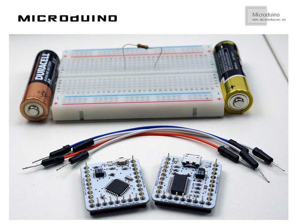
*Other hardware equipment | *Other hardware equipment | ||
| − | ** | + | **1x AA Battery |
| − | **Breadboard | + | **1x Box of breadboard jumper wires |
| − | **1kΩ resistor | + | **1x Breadboard |
| − | **USB Data cable | + | **1x 1kΩ resistor |
| + | **1x USB Data cable | ||
[[File:lesson9All.jpg|600px|center|thumb]] | [[File:lesson9All.jpg|600px|center|thumb]] | ||
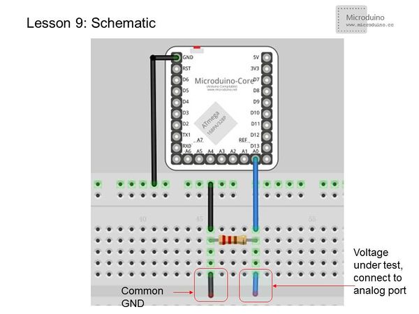
| − | == | + | ==Experiment Schematic== |
[[File:less0n9-schematic.jpg|center|600px|thumb]] | [[File:less0n9-schematic.jpg|center|600px|thumb]] | ||
| − | |||
==Program== | ==Program== | ||
| 第28行: | 第28行: | ||
void setup() | void setup() | ||
{ | { | ||
| − | Serial.begin( | + | Serial.begin(9600); //Set baud rate 9600 |
} | } | ||
void loop() | void loop() | ||
| 第34行: | 第34行: | ||
int V1 = analogRead(A0); | int V1 = analogRead(A0); | ||
| − | // Read the voltage | + | // Read the voltage data from A0 and store it in variable V1. The voltage range is 0-5V and returns values 0-1024. |
float vol = V1*(5.0 / 1023.0); | float vol = V1*(5.0 / 1023.0); | ||
| − | //Convert the V1 to | + | //Convert the V1 to the voltage value and store it in vol |
if (vol == temp) | if (vol == temp) | ||
//Use to filter duplicate data, Only the voltage value and the last isn't same then output the value. | //Use to filter duplicate data, Only the voltage value and the last isn't same then output the value. | ||
| 第51行: | 第51行: | ||
} | } | ||
</source> | </source> | ||
| − | We | + | We didn't use the map() function in this example, but you can try it yourself! |
==Result== | ==Result== | ||
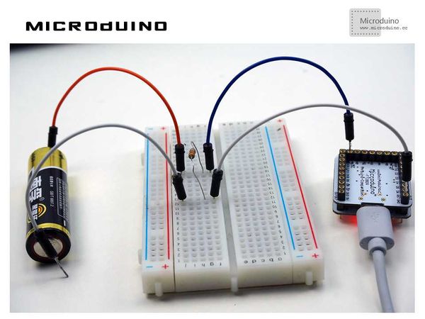
| − | When the measured voltage | + | When the measured voltage changes, refresh the data every second. It is normal if there is a difference between two measurements of the same battery. This is because this is still simply a low accuracy test. If you need a high accuracy test, you can take a look at: |
| − | |||
http://www.hacktronics.com/Tutorials/arduino-current-sensor.html | http://www.hacktronics.com/Tutorials/arduino-current-sensor.html | ||
[[File:lesson9Result.jpg|600px|center|thumb]] | [[File:lesson9Result.jpg|600px|center|thumb]] | ||
| + | |||
==Video== | ==Video== | ||
| + | https://www.youtube.com/watch?v=bhaj_QhRE-Q | ||
|} | |} | ||
| − | |||
| − | |||
2015年7月27日 (一) 00:49的最新版本
| Language | English |
|---|
ObjectivePreviously, we introduced analogRead() and its return values of 0~1024. In this lesson, we will use the analog port of Microduino-Core to make a multimeter with the range of 0-5 V. Important: The design of this experiment does not have an effective protection circuit. Please do not use more than two AA batteries and do not use the circuit to measure a lithium battery or any other power supply! Equipment
Experiment SchematicProgramfloat temp; // Define a float variable temp to save data.
void setup()
{
Serial.begin(9600); //Set baud rate 9600
}
void loop()
{
int V1 = analogRead(A0);
// Read the voltage data from A0 and store it in variable V1. The voltage range is 0-5V and returns values 0-1024.
float vol = V1*(5.0 / 1023.0);
//Convert the V1 to the voltage value and store it in vol
if (vol == temp)
//Use to filter duplicate data, Only the voltage value and the last isn't same then output the value.
{
temp = vol; //Compared, then store in temp variable "temp"
}
else
{
Serial.print(vol); //Serial output voltage, nowrap
Serial.println(" V"); //Serial output character "V", and wrap
temp = vol;
delay(1000); //Wait for 1s, use to refresh the data
}
}
We didn't use the map() function in this example, but you can try it yourself! ResultWhen the measured voltage changes, refresh the data every second. It is normal if there is a difference between two measurements of the same battery. This is because this is still simply a low accuracy test. If you need a high accuracy test, you can take a look at: http://www.hacktronics.com/Tutorials/arduino-current-sensor.html Video |


