“Lesson 8--Microduino "Pulse Recorder"”的版本间的差异
(→Experiment Schematic) |
|||
| (未显示同一用户的1个中间版本) | |||
| 第27行: | 第27行: | ||
==Experiment Schematic== | ==Experiment Schematic== | ||
[[File:lesson8-schematic.jpg|600px|center|thumb]] | [[File:lesson8-schematic.jpg|600px|center|thumb]] | ||
| − | + | This schematic uses the internal pull-up. We also connected an external ceramic capacitor for stabilization. | |
==Program== | ==Program== | ||
| 第76行: | 第76行: | ||
==Result== | ==Result== | ||
| − | For stabilization, add a ceramic capacitor in the signal change port. You | + | For stabilization, add a ceramic capacitor in the signal change port. You will be able to see better results. |
[[File:lesson8-capacitance.jpg|600px|center|thumb]] | [[File:lesson8-capacitance.jpg|600px|center|thumb]] | ||
[[File:lesson8Result.jpg|600px|center|thumb]] | [[File:lesson8Result.jpg|600px|center|thumb]] | ||
2015年7月15日 (三) 00:11的最新版本
| Language | English |
|---|
目录ObjectiveIn lesson 3, you learned how to use a button and avoid the issue of electrical noise. The solution was to add a short delay. However, this solution has a disadvantage. Different people will take different amounts of time to press a button. That means the delay must be different for different people, too. This lesson will teach you how to get the duration that a button is pressed down. This program uses pulse timing calculation. In addition, you will learn about Arduino's serial port to monitor the data. Equipment
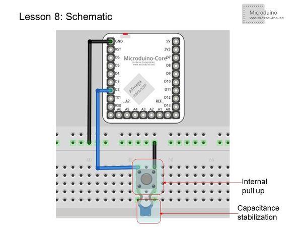
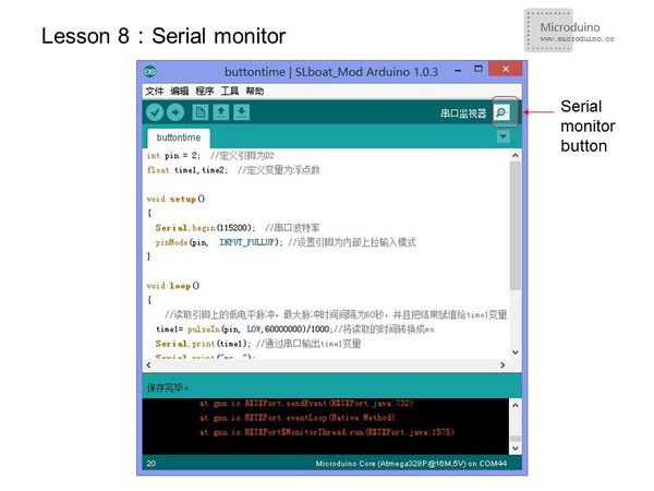
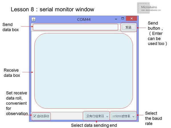
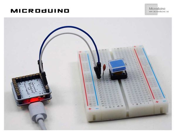
PulsePulse is a rapid, transient change in the amplitude of a signal from a baseline value to a higher or lower value, followed by a rapid return to the baseline value. In Microduino, pulse is simply a digital signal which changes between high and low in a cyclical pattern. Pulse timing is often used to calculate the speed in electronic components. Experiment SchematicThis schematic uses the internal pull-up. We also connected an external ceramic capacitor for stabilization. Programint pin = 2; //Define Pin D2
float time1,time2; //Define variables to float
void setup()
{
Serial.begin(115200); //Serial port baud rate
pinMode(pin, INPUT_PULLUP); //Set pin to input mode with the internal pull-up
}
void loop()
{
//Read low pulse from the pin, the maximum pulse interval is 60 seconds, and assign the result to the variable time1
time1= pulseIn(pin, LOW, 60000000)/1000; //Convert the time to ms
Serial.print(time1); //Output the time1 by serial
Serial.print("ms ");
time2= pulseIn(pin, LOW,60000000)/1000.0; //Convert the time to ms
Serial.print(time2); //Output time1 by serial
Serial.println("ms"); //Output time2 by serial and start a new line
}
Serial MonitoringOpen the serial port monitor
pulseIn() usage
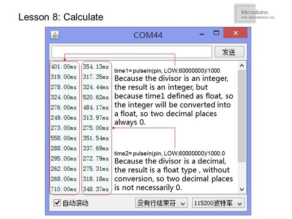
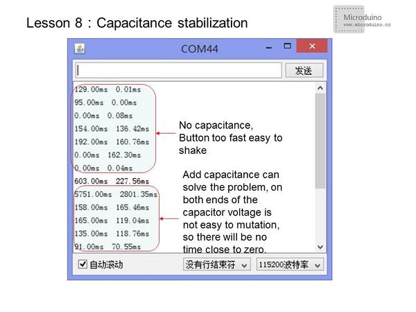
ResultFor stabilization, add a ceramic capacitor in the signal change port. You will be able to see better results. Video |
